background image

4

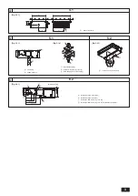
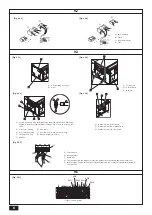
A

  Cut here

B

  Remove brazed cap

A

A

E

C

F

B

D

A

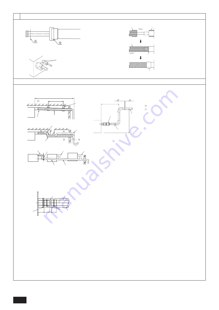
  Thermal insulation

B

  Pull out insulation

C

  Wrap with damp cloth

D

  Return to original position

E

  Ensure that there is no gap here

F

  Wrap with insulating tape

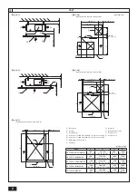
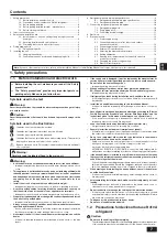
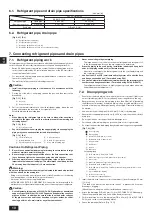
[Fig. 7.1.1]

7.1

[Fig. 7.1.3]

B

J

O

N

F

Max. 300 mm [11-

13

/

16

 in]

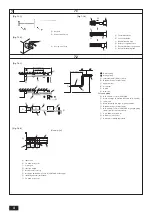
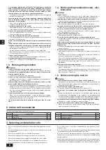
[Fig. 7.2.1]


Correct piping


Wrong piping

A

  Insulation (9 mm [3/8 in] or more)

B

  Downward slope (1/100 or more)

C

  Support metal

K

  Air bleeder

L

 Raised

M

  Odor trap

  Grouped piping

D

  O. D. ø32 mm [1-1/4 in] PVC TUBE

E

  Make it as large as possible. About 10 cm [3-15/16 in].

F

  Indoor unit

G

  Make the piping size large for grouped piping.

H

  Downward slope (1/100 or more)

I

  O. D. ø38 mm [1-1/2 in] PVC TUBE for grouped piping. 


(9 mm [3/8 in] or more insulation)

J

  Up to 700 mm [27-9/16 in]

N

  Drain hose (accessory)

O

  Horizontal or slightly upgradient

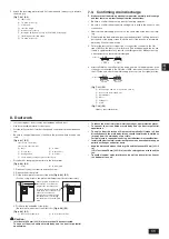
7.2

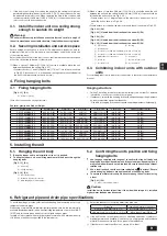
[Fig. 7.2.2]

C

B

A

L

D

D

D

E

K

M

B

H

I

Max. 20 m [65 ft]

1.5-2 m [5-7 ft]

G

F

F

F

B

C

D

D

G

F

E

H

A

35

[1-

13

/

32

]

32

[1-

1

/

4

]

25

[1]

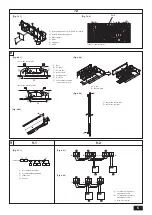
A

  Indoor unit 

B

  Tie band (accessory)

C

  Visible part 

D

  Insertion margin

E

  Drain hose (accessory)

F

  Drain pipe (O.D. ø32 mm [1-1/4 in] PVC TUBE, field supply)

G

  Insulating material (field supply)

H

  Tie band (accessory)

A

[Fig. 7.1.2]

A

  Cool by a wet cloth

7

(Unit: mm [in])

Summary of Contents for CITY MULTI PEFY-P06NMAU-E3

Page 1: ...MANUAL For safe and correct use please read this installation manual thoroughly before installing the air conditioner unit MANUEL D INSTALLATION Veuillez lire le manuel d installation en entier avant d installer ce climatiseur pour éviter tout accident et vous assurer d une utilisation correcte ...

Page 2: ... 1 8 400 500 15 3 4 19 11 16 1500 59 1 16 2000 78 3 4 PEFY P54NMAU E3 1600 63 500 600 19 11 16 23 5 8 1700 66 15 16 2200 86 5 8 Unit mm in G H I F 700 27 9 16 450 17 3 4 475 18 3 4 450 17 3 4 Q 50 150 2 5 15 16 450 17 3 4 450 17 3 4 100 200 3 15 16 7 7 8 Min 300 11 13 16 P E A D H G Min 20 13 16 Min 10 7 16 B C A B J P 50 2 R 777 30 5 8 450 17 3 4 475 18 3 4 700 27 9 16 50 2 Min 300 11 13 16 E A I...

Page 3: ...draining A Unit body B Lifting machine C Nuts field supply D Washers square accessory E M10 hanging bolt field supply 5 5 2 Fig 5 1 1 Fig 5 1 2 5 1 6 6 2 Fig 6 2 1 A Center of gravity A Indoor unit s bottom surface A Y X L W A Z C D C E D B A 137 5 7 16 67 2 5 8 239 9 7 16 357 14 1 16 122 4 13 16 33 1 5 16 41 1 5 8 217 8 9 16 C A B D Fig 5 2 1 Unit mm in ...

Page 4: ...as large as possible About 10 cm 3 15 16 in F Indoor unit G Make the piping size large for grouped piping H Downward slope 1 100 or more I O D ø38 mm 1 1 2 in PVC TUBE for grouped piping 9 mm 3 8 in or more insulation J Up to 700 mm 27 9 16 in N Drain hose accessory O Horizontal or slightly upgradient 7 2 Fig 7 2 2 C B A L D D D E K M B H I Max 20 m 65 ft 1 5 2 m 5 7 ft G F F F B C D D G F E H A 3...

Page 5: ... to 1 5 8 in B Remove the water supply port C About 2500 cc D Water E Filling port F Screw Fig 8 0 2 SWE Fig 7 3 2 Fig 8 0 3 Fig 8 0 4 Indoor controller board A B F C D E A B G F A C E D A B G C E A F D A B A Filter B Bottom plate C Nail for the bottom inlet D Nail for the rear inlet C D A In case of rear inlet B In case of bottom inlet A Duct B Air inlet C Access door D Canvas duct E Ceiling surf...

Page 6: ...together to the S terminal Dead end connection E Insulation tape To keep the earth wire of the shielded cable from coming in contact with the transmis sion terminal 9 3 Fig 9 3 3 Fig 9 3 4 Fig 9 3 5 C Terminal box D Knockout hole E Remove A Screw holding cover 1pc B Cover Fig 9 3 1 Fig 9 3 2 A Non polarized B TB15 C Remote Controller D TB5 Fig 9 2 3 Fig 9 2 4 2 S M2 M1 A B D 1 DC10 13V A B 1 2 L1 ...

Page 7: ...tall the accessories Improper installation by the user may result in water leakage electric shock or fire Never repair the unit If the air conditioner must be repaired consult the dealer If the unit is repaired improperly water leakage electric shock or fire may result If the supply cord is damaged it must be replaced by the manufacturer its service agent or similarly qualified persons in order to...

Page 8: ...e its parts When installing the unit in a hospital communication station or similar place provide sufficient protection against noise The inverter equipment private power generator high frequency medical equipment or radio communication equipment may cause the air conditioner to operate erroneously or fail to operate On the other hand the air conditioner may affect such equipment by creating noise...

Page 9: ...e W mm in L mm in X mm in Y mm in Z mm in Product Weight kg lb PEFY P06NMAU E3 643 25 5 16 754 29 11 16 330 13 300 11 13 16 130 5 1 8 22 49 PEFY P08NMAU E3 643 25 5 16 754 29 11 16 330 13 300 11 13 16 130 5 1 8 22 49 PEFY P12NMAU E3 643 25 5 16 754 29 11 16 330 13 300 11 13 16 130 5 1 8 22 49 PEFY P15NMAU E3 643 25 5 16 954 37 9 16 340 13 3 8 375 14 3 4 130 5 1 8 26 58 PEFY P18NMAU E3 643 25 5 16 ...

Page 10: ...or accidents resulting from the use of the wrong type of refrigerant Caution Use refrigerant piping made of C1220 Cu DHP phosphorus deoxidized copper as specified in the JIS H3300 Copper and copper alloy seamless pipes and tubes In addition be sure that the inner and outer surfaces of the pipes are clean and free of hazardous sulphur oxides dust dirt shaving particles oils moisture or any other co...

Page 11: ...ulation to inlet duct flange and outlet duct to prevent condensa tion Be sure to change the position of air filter to the position where it can be serv iced Fig 8 0 1 P 5 A In case of rear inlet B In case of bottom inlet A Duct B Air inlet C Access door D Canvas duct E Ceiling surface F Air outlet G Leave distance enough to prevent short cycle Procedure for changing the rear inlet to the bottom in...

Page 12: ...length 200 m Maximum length of transmission lines for centralized control and indoor outdoor transmission lines Maximum length via indoor units 500 m MAX The maximum length of the wiring between power supply unit for transmission lines on the transmission lines for centralized control and each outdoor unit and system controller is 200 m When 10 m is exceeded use cables with the same specification ...

Page 13: ...ved it cannot operate normally 9 4 External I O specifications Caution 1 Wiring should be covered by insulation tube with supplementary insula tion 2 Use relays or switches with IEC or equivalent standard 3 The electric strength between accessible parts and control circuit should have 2750 V or more 9 2 Connecting remote controller indoor and outdoor transmission cables Connect indoor unit TB5 and...

Page 14: ... varies with the system at site Set them referring to the Data Book 9 7 Sensing room temperature with the built in sensor in a remote controller If you want to sense room temperature with the built in sensor in a remote control ler set SW1 1 on the control board to ON The setting of SW1 7 and SW1 8 as necessary also makes it possible to adjust the air flow at a time when the heating thermometer is...

Page 15: ...ress telephone number on this manual before handing it to the customer This product is designed and intended for use in the residential commercial and light industrial environment HEAD OFFICE TOKYO BLDG 2 7 3 MARUNOUCHI CHIYODA KU TOKYO 100 8310 JAPAN ...

Page 16: ... F OPERATION MANUAL For safe and correct use please read this operation manual thoroughly before operating the air conditioner unit MANUEL D UTILISATION Pour une utilisation correcte sans risques veuillez lire le manuel d utilisation en entier avant de vous servir du climatiseur ...

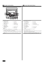
Page 17: ...F FILTER CHECK CLEAR MENU ON OFF TEST TEMP CLOCK OPERATION BACK DAY MONITOR SET 1 2 3 4 D 5 6 8 9 C 0 A B 7 Remote controller Button Touche Commande à distance GB F 1 Touche Réglage de la température 2 Touche Timer Menu 3 Touche Mode Touche Monitor Set Touche Back 4 Touche Timer On Off 5 Touche Louvre Touche Set Day Touche Operation 6 Touche Vitesse du ventilateur 7 Touche Commande des ailettes 8 ...

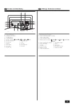
Page 18: ...pièce N Réglage des ailettes O Vitesse du ventilateur P Témoin de fonctionnement Remote controller Display Affichage Commande à distance GB F A Current time Timer time B Centralized control indicator C Timer OFF indicator D Timer mode indicator E Operation mode display COOL DRY AUTO FAN HEAT F Function mode indicator G Preset temperature H Power indicator I Louver J Ventilation K Filter sign L Sen...

Page 19: ...4 4 2 In case of bottom inlet En cas d entrée sur le dessous 1 In case of rear inlet En cas d entrée arrière A Filter Filtre Air Flow Flux d air A 1 A 2 Fig A ...

Page 20: ...use of the wrong type of refrigerant 1 Outdoor unit Warning The outdoor unit must be installed on a stable level surface in a place where there is no accumulation of snow leaves or rubbish Do not stand on or place any items on the unit You may fall down or the item may fall causing injury Caution The outdoor unit should be installed in a location where air and noise emitted by the unit will not di...

Page 21: ...it consult your dealer If pipes are removed incorrectly refrigerant fluorocarbon gas may blow out and come into contact with your skin causing injury Releasing refrigerant into the atmosphere also damages the environment 2 Names and functions of various parts Attachment and detachment of filter Fig A P 4 3 How to operate Before starting operation Start running after the PLEASE WAIT display has dis...

Page 22: ...on according to the change of the room temperature and automatically repeat ON OFF 2 When reaching room temperature of your choice Both the compressor and indoor fan stop When stop continues for 10 minutes the compressor and indoor fan are oper ated for 3 minutes to keep the humidity low For heating Press the 3 Mode BACK Button to bring up the HEAT display Regarding displays during heating operati...

Page 23: ... Heating operation starts after ending defrosting operation It runs briefly but soon stops The CHECK and check code flashes on the liquid crystal display There are some obstacles at the air inlet and outlet of the indoor and outdoor units Rerun after removal The filter is filled with dust and dirt Rerun after cleaning the filter Refer to Caring for the machine The sound of the exhaust and rotation...

Page 24: ...f the professional engineering work required for transferring the instal lation Caution When moving or reinstalling the air conditioner consult with your dealer Defective installation can result in electric shock fire etc Regarding noise In installing work choose a place that can fully bear the weight of the air con ditioner and where noise and vibration can be reduced Choose a place where cool or...

Page 25: ...The operating noise is the data that was obtained in an anechoic room Item Model P36NMAU E3 P48NMAU E3 P54NMAU E3 Power source 208 230V 60Hz Cooling capacity 1 Heating capacity 1 Btu h 36 000 40 000 48 000 54 000 54 000 60 000 kW 10 6 11 7 14 1 15 8 15 8 17 6 Dimension Height mm in 250 9 13 16 Width mm in 1 400 55 1 8 1 600 63 Depth mm in 732 28 7 8 Net weight kg lb 39 86 42 93 Fan Airflow rate Lo...

Page 26: ...ress telephone number on this manual before handing it to the customer This product is designed and intended for use in the residential commercial and light industrial environment HEAD OFFICE TOKYO BLDG 2 7 3 MARUNOUCHI CHIYODA KU TOKYO 100 8310 JAPAN ...

Reviews: