10
PEFY-P200·250VMH-E
Unit : mm
2
1
3
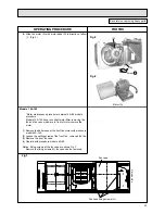
Note1.Use M10 screw for the lifting bolt (field supply). 2.Keep the service space for the maintenance from the bottom when the heat exchanger is cleaned. 3.Make sure to install the air filter(field supply) on the air intake side. In case field supplied air filter is used, attach it where the filter service is easily done.
T
erminal bed (Power source)
T
erminal bed
(T
ransmission)
Lifting bolt
24
10
50x6=300
50x7=350
327
30
21-ø3
22-ø3
1250
50x21=1050
25
102
50x20= 1000
50
15
100
420
35
20
1120
10
1067
15
29
470
340
105
44
164
20
41
489
422
95
249
23
1326(Lifting bolt pitch)
1372
1100
420
1124
1034(Lifting bolt pitch)
60
340
1100
Drain hole
Control box
Drain hole (option)
Keep duct-work length 850mm or more.
Air outlet
Air inlet
Lower than 550mm
Lower than 300mm
3
When installing the drain water lifting-up mech(option).
Refrigerant piping flare connection(gas M copper tube):HP
··············
Refrigerant piping flare connection(liquid N copper tube):LP
············
Drain hose 32mm(1-1/4inch) <flexible joint 200mm> (accessory)
·····
1
2
3
Make the access door at the appointed position properly for service maintenance.
Access door
Ceiling surface
Higher than 20mm
Higher than 20mm
150~200700
50
50
1359
Access door
625
Note 2
Reguired space for service and maintenance
450
100~200
450
170mm
±
5mm
(Actual Length)
Model
A
B
P200VMH-E
ø
19.05
ø
25.4
ø
22.2
ø
28.58
ø
9.52
ø
12.7
ø
9.52
ø
12.7
P250VMH-E
✻
1
✻
2
✻
1
✻
2
✻
1
✻
2
✻
1
✻
2
✻
1:R410A outdoor unit
✻
2:The other outdoor unit


