GB
2
►
Before installing the unit, make sure you read all the “Safety precau-
tions”.
►
Please report to your supply authority or obtain their consent before
connecting this equipment to the power supply system.
1. Safety precautions
Contents
1. Safety precautions ........................................................................................ 2
2. Installation location ....................................................................................... 2
3. Installing the indoor unit................................................................................ 3
4. Refrigerant pipe ........................................................................................... 4
5. Drainage piping work .................................................................................... 5
6. Embedding the indoor unit in a wall.............................................................. 6
7. Electrical work .............................................................................................. 7
8. Test run ......................................................................................................... 8
9. Air outlet selection ........................................................................................ 9
Warning:
Describes precautions that must be observed to prevent danger of injury or
death to the user.
Caution:
Describes precautions that must be observed to prevent damage to the unit.
After installation work has been completed, explain the “Safety Precautions,” use,
and maintenance of the unit to the customer according to the information in the
Operation Manual and perform the test run to ensure normal operation. Both the
Installation Manual and Operation Manual must be given to the user for keeping.
These manuals must be passed on to subsequent users.
: Indicates an action that must be avoided.
: Indicates that important instructions must be followed.
: Indicates a part which must be grounded.
: Indicates that caution should be taken with rotating parts.
: Indicates that the main switch must be turned off before servicing.
: Beware of electric shock.
: Beware of hot surface.
ELV
: At servicing, please shut down the power supply for both the Indoor and
Outdoor Unit.
Warning:
Carefully read the labels affixed to the main unit.
Warning:
• Ask the dealer or an authorized technician to install the air conditioner.
• Install the unit at a place that can withstand its weight.
•
Use only specified cables for wiring. The wiring connections must be
made securely with no tension applied on the terminal connections. Also,
never splice the cables for wiring (unless otherwise indicated in this docu-
ment).
Failure to observe these instructions may result in overheating or a fire.
• Use only accessories authorized by Mitsubishi Electric and ask the dealer
or an authorized technician to install them.
• Do not touch the heat exchanger fins.
• Install the air conditioner according to this Installation Manual.
• Have all electric work done by a licensed electrician according to local
regulations.
• If the air conditioner is installed in a small room, measures must be taken
to prevent the refrigerant concentration from exceeding the safety limit
even if the refrigerant should leak.
• The cut face punched parts may cause injury by cut, etc. The installers are
requested to wear protective equipment such as gloves, etc.
•
When installing or relocating, or servicing the outdoor unit, use only the
specified refrigerant (R410A) to charge the refrigerant lines. Do not mix it
with any other refrigerant and do not allow air to remain in the lines.
If air is mixed with the refrigerant, then it can be the cause of abnormal high
pressure in the refrigerant line, and may result in an explosion and other
hazards.
The use of any refrigerant other than that specified for the system will cause
mechanical failure or system malfunction or unit breakdown. In the worst
case, this could lead to a serious impediment to securing product safety.
Caution:
• Do not use the existing refrigerant piping, when use R410A or R407C refrigerant.
• Use ester oil, either oil or alkylbenzene (small amount) as the refrigerator oil
to coat flares and flange connections, when use R410A or R407C refrigerant.
• Do not use the air conditioner where food, pets, plants, precision instru-
ments, or artwork are kept.
• Do not use the air conditioner in special environments.
• Ground the unit.
• Install an leak circuit breaker, as required.
• Use power line cables of sufficient current carrying capacity and rating.
• Use only a circuit breaker and fuse of the specified capacity.
• Do not touch the switches with wet fingers.
• Do not touch the refrigerant pipes during and immediately after operation.
• Do not operate the air conditioner with the panels and guards removed.
• Do not turn off the power immediately after stopping operation.
2. Installation location
The indoor unit should be supplied with the following accessories.
PART NUMBER
ACCESSORY
QUANTITY
1
Drain hose
1
2
Pipe cover
1
3
Band
2
4
Indoor unit mounting bracket
1
5
Fixing screw for
4
4 × 25 mm
5
6
Wood screw for the indoor unit fixation
4
7
Washer of
6
4
8
Felt tape (Used for left or left-rear piping)
1
9
MA Remote controller cable
1
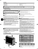
Fig. 2-1
(mm)
700
600
200
A
C
B
D
2.1. Outline dimensions (Indoor unit) (Fig. 2-1)
The unit must be securely installed on a structure that can sustain its weight.
Models
A
B
C
D
P20/25/32/40
100 mm or more
100 mm or more
100 mm or more
150 mm or below
from the floor
Warning:
Mount the indoor unit on a wall structure strong enough to withstand the
weight of the unit.
Note:
The phrase “Wired remote controller” in this installation manual refers only to the PAR-21MAA.
If you need any information for the other remote controller, please refer to either the installation manual or initial setting manual which
are included in these boxes.


