


5
8.2
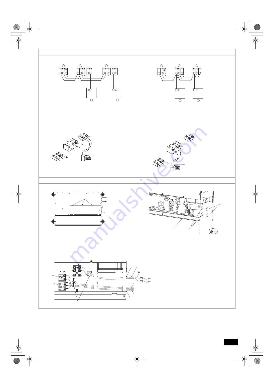
[Fig. 8.2.1]
[Fig. 8.2.2]
[Fig. 8.2.3]
[Fig. 8.2.4]
8.3
[Fig. 8.3.1]
[Fig. 8.3.2]
[Fig. 8.3.3]
TB5
TB15 TB5
TB15
S
M1M2
S
M1M2
TB3
M1M2
2
1
2
1
A
A
B
C
C
TB5
TB5
S
M1M2
S
M1M2
TB3
M1M2
A
A
B
C
C
A
Terminal block for indoor transmission cable
B
Terminal block for outdoor transmission cable
C
Remote controller
2
S
M2
M1
A
B
D
1
DC10~13V
A
B
1
2
L
N
C
D
A
S
M2
M1
B
1
2
L
N
DC24~30V
(A, B)
1
2
C
A
Non-polarized
B
TB15
C
Remote Controller
D
TB5
A
B
A
Screw holding cover (3pcs.)
B
Cover
C
B
A
A
Terminal bed box
B
Knockout hole
C
Remove
C
H
J
I
D
N
L
N
L
M1
12
M2
S
B
E
A
G
F
A
Use a cable tie to secure the cable.
B
Use PG bushing to keep the weight of the cable and
external force from being applied to the power supply
terminal connector.
C
Power source wiring
D
Use ordinary bushing
E
Power source terminal block
F
Terminal block for indoor transmission
G
Terminal block for remote controller
H
To 1-phase power source
I
Transmission line 30 VDC
J
Transmission line to the remote controller, terminal block
for indoor unit and BC controller
VZ79D813H01_DA.book 5 ページ 2018年12月3日 月曜日 午後5時17分


