


[
VII
Troubleshooting ]
- 15 -
HWE12100
GB
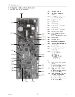
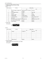
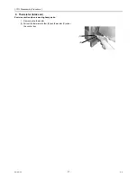
5. 1's and 10's digits
(1) SW11, SW12 (Rotary switch)
The use of a network remote controller (PAR-F27MEA) requires address setting.
1) Address board
Address settings must be made while the unit is stopped.
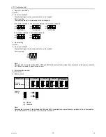
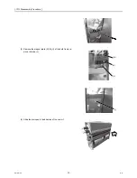
6. Connection No. setting
(1) SW14 (Rotary switch)
This switch is used when the unit connected to an R2 series of outdoor unit.
1) Address board
Note:
Changes to the dipswitches SW11, SW12 and SW14 must be made while the unit is stopped and the remote controller is OFF.
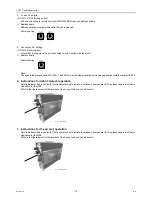
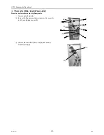
6. Instructions for debris removal operation
Details are described in section [9] “Instructions for debris removal operation” under chapter IX Troubleshooting in the Service
Handbook for the HBC.
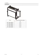
Refer to the figure below for the position of the air vent valve on the indoor unit.
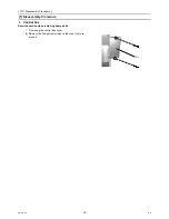
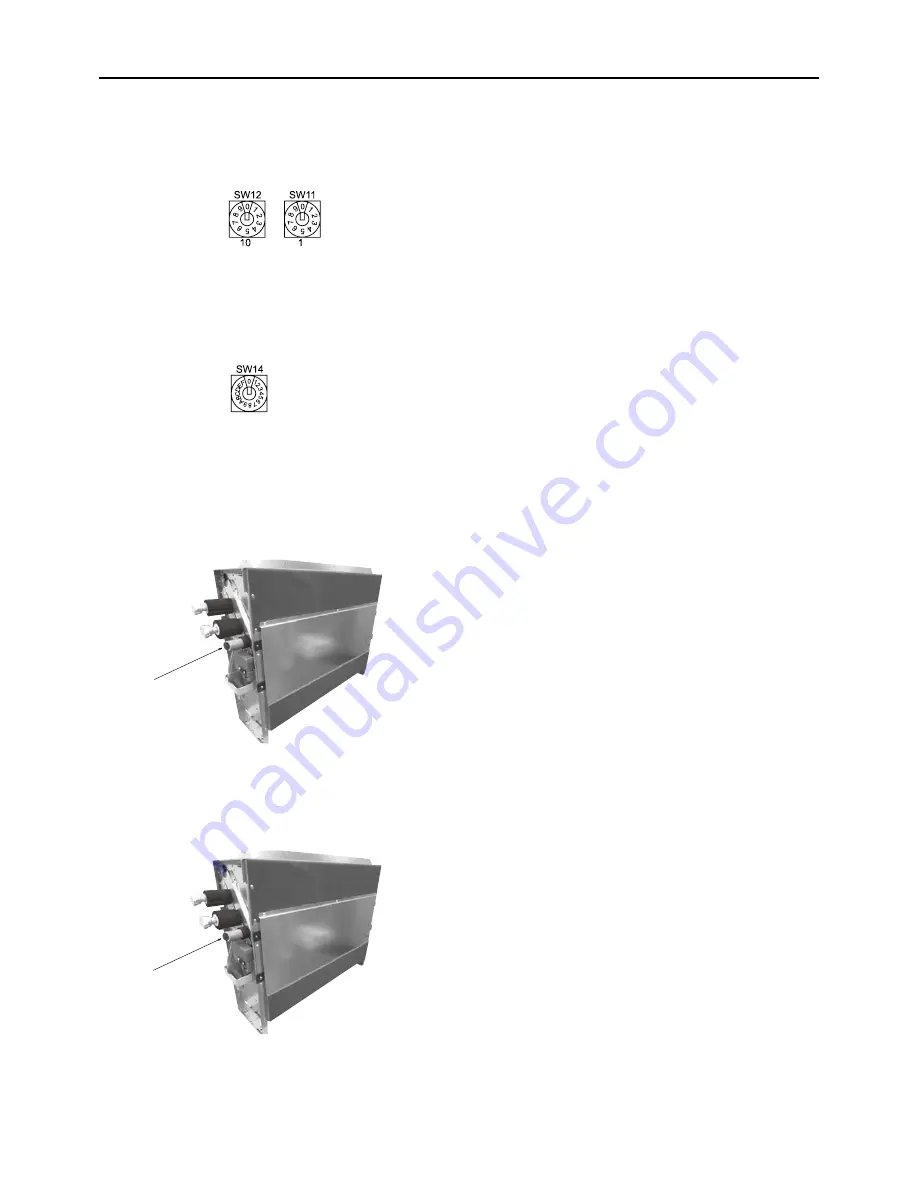
7. Instructions for the air vent operation
Details are described in section [9] “Instructions for debris removal operation” under chapter IX Troubleshooting in the Service
Handbook for the HBC.
Refer to the figure below for the position of the air vent valve on the indoor unit.
Factory setting
Factory setting
A
Air vent valve
A
A
Air vent valve
A
Summary of Contents for CITY MULTI PFFY-WP20VLRMM-E
Page 5: ...HWE12100 GB ...


