5
A
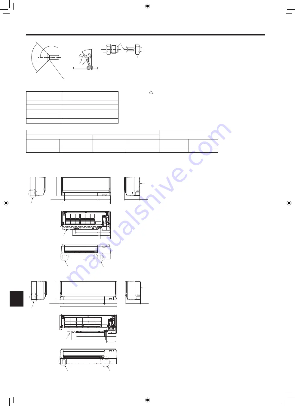
Flare cutting dimensions
Copper pipe O.D.
(mm, inch)
Flare dimensions øA dimensions
(mm, inch)
ø6.35, 1/4
8.7 - 9.1, 11/32 - 23/64
ø9.52, 3/8
12.8 - 13.2, 1/2 - 33/64
ø12.7, 1/2
16.2 - 16.6, 41/64 - 21/32
ø15.88, 5/8
19.3 - 19.7, 49/54 - 25/32
ø19.05, 3/4
22.9 - 23.3, 15/16 - 61/64
B
Refrigerant pipe sizes & Flare nut tightening torque
R410A
Flare nut O.D.
Liquid pipe
Gas pipe
Pipe size O.D.
(mm, inch)
Tightening torque.
(N·m, ft·lbs)
Pipe size O.D.
(mm, inch)
Tightening torque.
(N·m, ft·lbs)
Liquid pipe
(mm, inch)
Gas pipe
(mm, inch)
ODø6.35, 1/4
14 - 18, 10 - 13
ODø12.7, 1/2
49 - 61, 35 - 44
17, 43/64
26, 1-1/32
C
Apply refrigerating machine oil over the entire flare seat surface.
4. Installing the refrigerant piping
A
B
C
B
Fig. 4-1
4.1. Connecting pipes (Fig. 4-1)
• When commercially available copper pipes are used, wrap liquid and gas pipes
with commercially available insulation materials (heat-resistant to 100 °C, 212 °F
or more, thickness of 12 mm, 1/2 inch or more).
• Apply thin layer of refrigerant oil to pipe and joint seating surface before
tightening flare nut.
• Use two wrenches to tighten piping connections.
• Use refrigerant piping insulation provided to insulate indoor unit connections.
Insulate carefully.
• Do not apply refrigerating machine oil to the screw portions.
(This will make the flare nuts more apt to loosen.)
• Use flare nut installed to this indoor unit.
Warning:
When installing the unit, securely connect the refrigerant pipes before
starting the compressor.
4.2. Positioning refrigerant and drain piping (Fig. 4-2)
A
Gas pipe
* Indicates the condition with accessories mounted.
B
Liquid pipe
C
Drain hose (Effective length: 500 mm, 19-11/16 inch)
D
Left-side piping knockout hole
E
Lower piping knockout hole
F
Mount board
1
45°±2°
90°±0.5°
R0.4-R0.8
(R1/64-R1/32)
øA
5 (13/64)
237 (9-11/32)
299 (11-25/32)
199 (7-53/64)
525 (20-43/64)
773 (30-7/16)
160 (6-19/64)
178 (7-1/64)
423 (16-21/32)
360 (14-11/64)
192 (7-9/16)
D
E
E
F
5 (13/64)
237 (9-11/32)
199 (7-53/64)
650 (25-19/32)
299 (11-25/32)
898 (35-3/8)
160 (6-19/64)
178 (7-1/64)
533 (20-63/64) (
B
)
450 (17-23/32) (
A
)
192 (7-9/16)
49 (1-15/16)
49 (1-15/16)
D
E
E
F
C
C
■
PKFY-P04/06/08/12NLMU
■
PKFY-P15/18NLMU
Fig. 4-2
LEFT
FRONT
FRONT(OPEN THE GRILLE)
BOTTOM
LEFT
FRONT
FRONT(OPEN THE GRILLE)
BOTTOM
RIGHT
RIGHT
mm (inch)
mm (inch)
en
RH79A034H02_en.indd 5
2019/12/16 9:54:22
006


