7
en
5. Electrical work
A
B
B
F
A
C
D
[
1
]
[
2
]
[
3
]
E
S
R
A
A
A
I
G
[
4
]
[
5
]
H
K
J
A
A-A
10
A
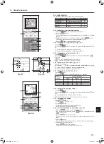
Fig. 5-1
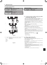
5.1. Indoor unit (Fig. 5-1)
1. Loosen the two screws securing the electrical wiring service panel, and then turn
the electrical wiring service panel. [Fig. 5-1
1
]
2. Loosen the one screw securing the electrical wiring service panel at the cable
entry (remote controller cable and indoor-outdoor connection cable), and then
turn the service panel to the position shown in the diagram. [Fig. 5-1
2
]
3. Loosen the two screws securing the electrical box cover, then slide the electrical
box cover. [Fig. 5-1
3
]
4. Pass and wire the power cable and the earth cable through the wiring entries
given in the diagram. [Fig. 5-1
4
]
5. Pass and wire the remote controller cable and the indoor - outdoor connection
cable through the wiring entries given in the diagram. [Fig. 5-1
5
, Fig. 5-2, Fig. 5-3]
• Put the sheath portion of the power cable, earth cable and the indoor - outdoor
connection cable into the electrical box.
• Refer to 5.2., 5.3. and 5.4. for the connection.
• Do not allow slackening of the terminal screws.
Screw tightening torque
Tightening torque (N·m)
Remote controller terminal board
1.2 ± 0.1
Indoor-outdoor connection terminal board
1.2 ± 0.1
Power terminal board
1.6 ± 0.1
Earth cable
1.6 ± 0.1
• Leave excess cable so that the electrical box can be suspended below the unit
during servicing (approx. 50 to 100 mm).
A
Electrical wiring service panel
B
Screw
C
Electrical box cover
D
Temporary hook for electrical box cover
E
Screw
F
Slide direction of the electrical box cover
G
Entry for power cable
H
Secure with the cable strap.
I
Earth cable
J
Power terminal
K
Entry for wired remote controller and indoor-outdoor connection cable
L
Drain Pan
M
Length of the cable not covered by the indoor - outdoor connection cable sheath.
N
Secure with the cable strap
O
Wired remote controller terminal
P
Indoor - outdoor connection terminal
Caution:
• Wiring for remote controller cable shall be apart (5 cm or more) from power
source wiring so that it is not influenced by electric noise from power source
wiring.
12
J
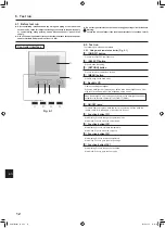
Fig. 5-2
• The U-shaped groove opens if you push the screw head after the screw is loosened.
10-15
80 - 100
M
N
Secure the remote controller cable and indoor-outdoor
connection cable with the cable strap.
If only one indoor-outdoor connection cable is connected,
secure it using the cable strap according to the dimen-
sions marked on the diagram.
10
10
12
P
O
MA remote controller terminal board
* Terminals 1 and 2 are non-polar.
Be sure to connect the wires (0.3 mm²) of
the remote controller cable at the locations
marked on the diagram.
Use round solderless
terminals with insulating
sleeves for the indoor-
outdoor connection cable.
ME remote controller
terminal block and
indoor-outdoor connection
terminal block
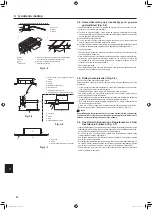
Fig. 5-3
Arrange the cables so that the
electrical wiring service panel is
not lifted up.
RG79F456H01_en.indd 7
2019/07/03 14:25:28
009
009


