background image

2

GB

Contents

1. Safety Precautions

  Before installing the unit, make sure you read all the 

“Safety Precautions”.

  The “Safety Precautions” provide very important 

points regarding safety. Make sure you follow them.

  Please report to or take consent by the supply 

authority before connection to the system.

•  Do not touch the upper air outlet vane or the lower air outlet 

damper during operation. Otherwise, condensation may form and 
the unit may stop operating.

Disposing of the unit

When you need to dispose of the unit, consult your dealer.

 Caution:

•  Do not use any sharp object to push the buttons, as this may 

damage the remote controller.

•  Never block or cover the indoor or outdoor unit’s air inlets or outlets.
•  Never wipe the remote controller with benzene, thinner chemical 

rags, etc.

•  Do not operate the unit for a long time in high humidity, e.g. 

leaving a door or window open. In the cool mode, if the unit is 
operated in a room with high humidity (80% RH or more) for a 
long time, water condensed in the air conditioner may drop and 
wet or damage furniture, etc.

•  Young children must be supervised to ensure that they do not 

play with the air conditioner.

•  If the refrigeration gas blows out or leaks, stop the operation of 

the air conditioner, thoroughly ventilate the room, and contact 
your dealer.

•  This appliance is intended to be used by expert or trained users 

in shops, in light industry and on farms, or for commercial use by 
lay persons.

•  This appliance is not intended for use by persons (including 

children) with reduced physical, sensory or mental capabilities, 
or lack of experience and knowledge, unless they have been 
given supervision or instruction concerning use of the appliance 
by a person responsible for their safety.

•  When installing or relocating, or servicing the air conditioner, use 

only the specified refrigerant (R410A) to charge the refrigerant 
lines. Do not mix it with any other refrigerant and do not allow air 
to remain in the lines.
If air is mixed with the refrigerant, then it can be the cause of 
abnormal high pressure in the refrigerant line, and may result in 
an explosion and other hazards. The use of any refrigerant other 
than that specified for the system will cause mechanical failure 
or system malfunction or unit breakdown. In the worst case, this 
could lead to a serious impediment to securing product safety.

 Warning:

•  These appliances are not accessible to the general public.
•  The unit must not be installed by the user. Ask the dealer or an 

authorized company to install the unit. If the unit is installed 
improperly, water leakage, electric shock or fire may result.

•  Do not stand on, or place any items on the unit. 
•  Do not splash water over the unit and do not touch the unit with 

wet hands. An electric shock may result.

•  Do not spray combustible gas close to the unit. Fire may result.
•  Do not place a gas heater or any other open-flame appliance 

where it will be exposed to the air discharged from the unit. 
Incomplete combustion may result.

•  Do not remove the front panel or the fan guard from the outdoor 

unit when it is running. 

•  Never repair the unit or transfer it to another site by yourself.
•  When you notice exceptionally abnormal noise or vibration, stop 

operation, turn off the power switch, and contact your dealer.

•  Never insert fingers, sticks etc. into the air inlets or outlets.
•  If you detect odd smells, stop using the unit, turn off the power 

switch and consult your dealer. Otherwise, a breakdown, electric 
shock or fire may result.

•  This air conditioner is NOT intended for use by children or infirm 

persons without supervision.

Symbols used in the text

 Warning:

Describes precautions that should be observed to prevent danger 
of injury or death to the user.

 Caution:

Describes precautions that should be observed to prevent damage 
to the unit.

Symbols used in the illustrations

 :  Indicates a part which must be grounded.

1. Safety Precautions ................................................................2
2. Parts Names 

..........................................................................3

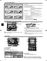
3. Screen Configuration 

.............................................................6

4.  Setting the Day of the Week and Time ..................................6
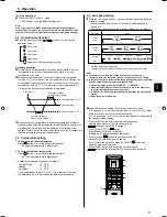
5. Operation 

...............................................................................6

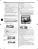
6. Timer .....................................................................................9

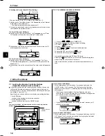
7. Other Functions 

...................................................................12

8. Function Selection 

...............................................................13

9.  Emergency Operation for Wireless Remote-controller ........17
10. Care and Cleaning ..............................................................17
11. Trouble  shooting ..................................................................19
12. Specifications ......................................................................21

Note:
The phrase “Wired remote controller” in this operation manual refers to the PAR-21MAA.
If you need any information for the other remote controller, please refer to the instruction book included in this box.

This symbol mark is for EU countries only.
This symbol mark is according to the directive 2002/96/EC Article 10 Information for users and Annex IV, and/or to the 
directive 2006/66/EC Article 20 Information for end-users and Annex II.

Your MITSUBISHI ELECTRIC product is designed and manufactured with high quality materials and components which can be 
recycled and/or reused. This symbol means that electrical and electronic equipment, batteries and accumulators, at their end-of-
life, should be disposed of separately from your household waste. If a chemical symbol is printed beneath the symbol (Fig. 1), this 
chemical symbol means that the battery or accumulator contains a heavy metal at a certain concentration. 
This will be indicated as follows: Hg: mercury (0,0005%),  Cd: cadmium (0,002%),  Pb: lead (0,004%) 
In the European Union there are separate collection systems for used electrical and electronic products, batteries and accumulators.
Please, dispose of this equipment, batteries and accumulators correctly at your local community waste collection/recycling centre.
Please, help us to conserve the environment we live in!

Note 

Fig.1

Summary of Contents for city multi PLFY-P-VCM-E2

Page 1: ...ire acondicionado para garantizar un uso seguro y correcto PARA EL USUARIO Español E ISTRUZIONI DI FUNZIONAMENTO Leggere attentamente questi istruzioni di funzionamento prima di avviare l unità per un uso corretto e sicuro della stessa PER L UTENTE Italiano I EΓXEIPIΔIO OΔHΓIΩN XPHΣEΩΣ Για ασφάλεια και σωστή χρήση παρακαλείστε διαβάσετε προσεχτικά αυτό το εγχειρίδιο χρήσεως πριν θέησετε σε λειτουρ...

Page 2: ...not splash water over the unit and do not touch the unit with wet hands An electric shock may result Do not spray combustible gas close to the unit Fire may result Do not place a gas heater or any other open flame appliance where it will be exposed to the air discharged from the unit Incomplete combustion may result Do not remove the front panel or the fan guard from the outdoor unit when it is ru...

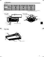
Page 3: ...ng life Long life Filter cleaning indication 100 hr 2 500 hr 2 500 hr PLFY P VCM E2 4 way Ceiling Cassette Filter Air intake Vane Air outlet This operation is available only using the remote controller that is able to set its Fan speed setting Auto PCFY P VKM E Ceiling Suspended Air outlet Louver Vane Air intake Filter Inside of Air intake Emergency operation switch Front grille Filter Air inlet A...

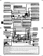
Page 4: ...been locked Clean the filter indicator Comes on when it is time to clean the filter Timer indicators The indicator comes on if the corresponding timer is set For purposes of this explanation all parts of the display are shown as lit During actual operation only the relevant items will be lit Note PLEASE WAIT message This message is displayed for approximately 3 minutes when power is supplied to th...

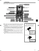
Page 5: ...ller or subject it to strong shocks In addition do not get the remote controller wet or leave it in a location with high humidity To avoid misplacing the remote controller install the holder included with the remote controller on a wall and be sure to always place the remote controller in the holder after use For explanation purposes all of the items that appear in the display are shown All items ...

Page 6: ... Day button 9 to set the day Each press advances the day shown at 3 Sun Mon Fri Sat 3 Press the appropriate Set Time button 1 as necessary to set the time As you hold the button down the time at 4 will increment first in minute intervals then in ten minute intervals and then in one hour intervals 4 After making the appropriate settings at Steps 2 and 3 press the Filter button 4 to lock in the valu...

Page 7: ...l mode In the same way if the room temperature remains 1 5 C or more below the set temperature for 3 minutes the air conditioner switches to heat mode Because the room temperature is automatically adjusted in order to maintain a fixed effective temperature cooling operation is performed a few degrees warmer and heating operation is performed a few degrees cooler than the set room temperature once ...

Page 8: ...m is waiting for the operation mode change to take effect 3 In heat mode when room temperature is higher than the temperature setting Manual To Change the Airflow s Left Right Direction The louver button 7 cannot be used Model PKFY P VKM E Stop the unit operation hold the lever of the louver and adjust to the desired direction Do not set to the inside direction when the unit is in the cooling or d...

Page 9: ...Timer Menu button 2 so that the Set Up appears on the screen at 2 Note that each press of the button toggles the display between Set Up and Monitor 3 Press the Timer On Off Set Day button 9 to set the day Each press advances the display at 3 to the next setting in the following sequence Sun Mon Tues Wed Thurs Fri Sat Sun Fri Sat Sun Mon Tues Wed Thurs Fri Sat 4 Press the or operation button 7 or 8...

Page 10: ...e only The air conditioner starts when the set time has elapsed Stop time only The air conditioner stops when the set time has elapsed Start stop times The air conditioner starts and stops at the respective elapsed times The simple timer start and stop can be set only once within a 72 hour period The time setting is made in hour increments Note 1 Weekly Timer Simple Timer Auto Off Timer cannot be ...

Page 11: ...er button 4 8 Press the Operation mode Back button 2 to return to the standard control screen 9 Press the Timer On Off button 9 to start the timer countdown When the timer is running the timer value is visible on the display Be sure that the timer value is visible and appropriate Viewing the Current Simple Timer Settings 1 Be sure that the simple timer indicator is visible on the screen at 1 2 Pre...

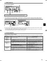
Page 12: ...er mode to stop the unit will cancel the timers If the current time has not been set the timer operation cannot be used 7 Other Functions C C TIME SUN FUNCTION PAR 21MAA ON OFF FILTER CHECK OPERATION CLEAR TEST TEMP MENU BACK DAY MONITOR SET CLOCK ON OFF 4 1 1 Locking function indicator 7 1 Locking the Remote Controller Buttons Operation function limit controller If you wish you can lock the remot...

Page 13: ...two remote controllers are connected to one group one controller must be set to sub 2 Use of clock setting CLOCK Setting the use or non use of clock function 3 Timer function setting WEEKLY TIMER Setting the timer type 4 Contact number setting for error situation CALL Contact number display in case of error Setting the telephone number 4 Display change DISP MODE SETTING 1 Temperature display C F s...

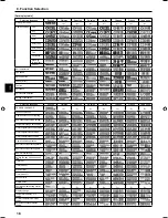
Page 14: ... setting is not used Initial setting value Operation lock setting is except On Off button Operation lock setting is All buttons The automatic mode is displayed when the operation mode is selected Initial setting value The automatic mode is not displayed when the operation mode is selected The temperature range limit is not active Initial setting value The temperature range can be changed on cool d...

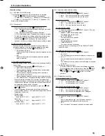
Page 15: ...imit setting press the button H The selected setting will flash and the temperature can be set Settable range Cool Dry mode Lower limit 19 C 30 C Upper limit 30 C 19 C Heat mode Lower limit 17 C 28 C Upper limit 28 C 17 C Automatic mode Lower limit 19 C 28 C Upper limit 28 C 19 C 8 Function Selection 4 3 Operation mode selection setting 1 Remote controller main sub setting To switch the setting pr...

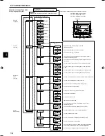
Page 16: ...hinese French Japanese CHANGE LANGUAGE Function selection Operation function limit setting Use of automatic mode setting Temperature range limit setting Limit temperature cool day mode Limit temperature heat mode Limit temperature auto mode Operation mode selection Remote controller setting MAIN Remote controller setting SUB Use of clock setting Setting the day of the week and time Timer set Timer...

Page 17: ...d When the filter display goes off the cumulative time is reset FILTER indicates the cleaning period when the air conditioner was used under general indoor air conditions by criteria time Since the degree of dirtiness depends on the environmental conditions clean the filter accordingly The filter cleaning period cumulative time differs with the model This indication is not available for wireless r...

Page 18: ...ution Never use gasoline benzene thinner scouring powder or any type of non neutral detergent as these substances may damage the unit s case PKFY P VKM E 1 Using both hands pull both the bottom corners of the inlet grille to open the grille then lift the filter until it clicks at the stop position 2 Hold the knobs on the filter and pull the filter up then pull it out downward Located in two places...

Page 19: ...oor unit During cool mode water may form and drip from the cool pipes and joints During heat mode water may form and drip from the heat exchanger During defrosting mode water on the heat exchanger evaporates and water vapor may be emitted The operation indicator does not appear in the remote controller display Turn on the power switch will appear in the remote controller display The air conditione...

Page 20: ...nditioner Do not attempt to repair this equipment by yourself Turn off the power switch immediately and consult your dealer Be sure to provide the dealer with the model name Warm air blows from the indoor unit intermittently when heat mode is off or during fan mode When another indoor unit is operating in heat mode the control valve opens and closes occasionally to maintain stability in the air co...

Page 21: ...oise level Low Middle High dB 28 30 31 28 31 35 28 31 37 29 33 38 30 34 39 Model PCFY P40VKM E PCFY P63VKM E PCFY P100VKM E PCFY P125VKM E Power source Voltage V Frequency Hz N 220 230 240 50 220 60 Capacity Cooling Heating kW 4 5 5 0 7 1 8 0 11 2 12 5 14 0 16 0 Dimension Height mm 230 Dimension Width mm 960 1280 1600 Dimension Depth mm 680 Net weight kg 24 32 36 38 Fan Airflow volume Low Middle2 ...

Page 22: ...e be sure to put the contact address telephone number on this manual before handing it to the customer Printed in Thailand RG79Y571H01 HEAD OFFICE TOKYO BLDG 2 7 3 MARUNOUCHI CHIYODA KU TOKYO 100 8310 JAPAN ...

Reviews: