26
0
5
9
4
8
3
7
2
6
1
0
5
9
4
8
3
7
2
6
1
0
5
9
4
8
3
7
2
6
1
0
5
9
4
8
3
7
2
6
1
0
8
F
7
E
6
D
5
C
4
B
3
A
2
9
1
0
8
F
7
E
6
D
5
C
4
B
3
A
2
9
1
Rotary switch
Rotary switch
SW14
Connection
No.
setting
SW11
1s digit
address
setting
SW12
10ths digit
address
setting
Pole
Operation by switch
How to set addresses
Example: If address is "3", remain SW12
(for over 10) at "0", and match SW11 (for 1 to 9)
with "3".
How to set branch numbers SW14 (Series R2 only)
Match the indoor unit’s refrigerant pipe with
the BC controller’s end connection number.
Remain other than series R2 at "0".
Remarks
<Initial setting>
SW12
10
SW11
1
SW12
SW11
SW14
SW14
<Initial setting>
Effective
timing
Before
power
supply
ON
Indoor controller board
Indoor controller board
10-3. TEST POINT DIAGRAM
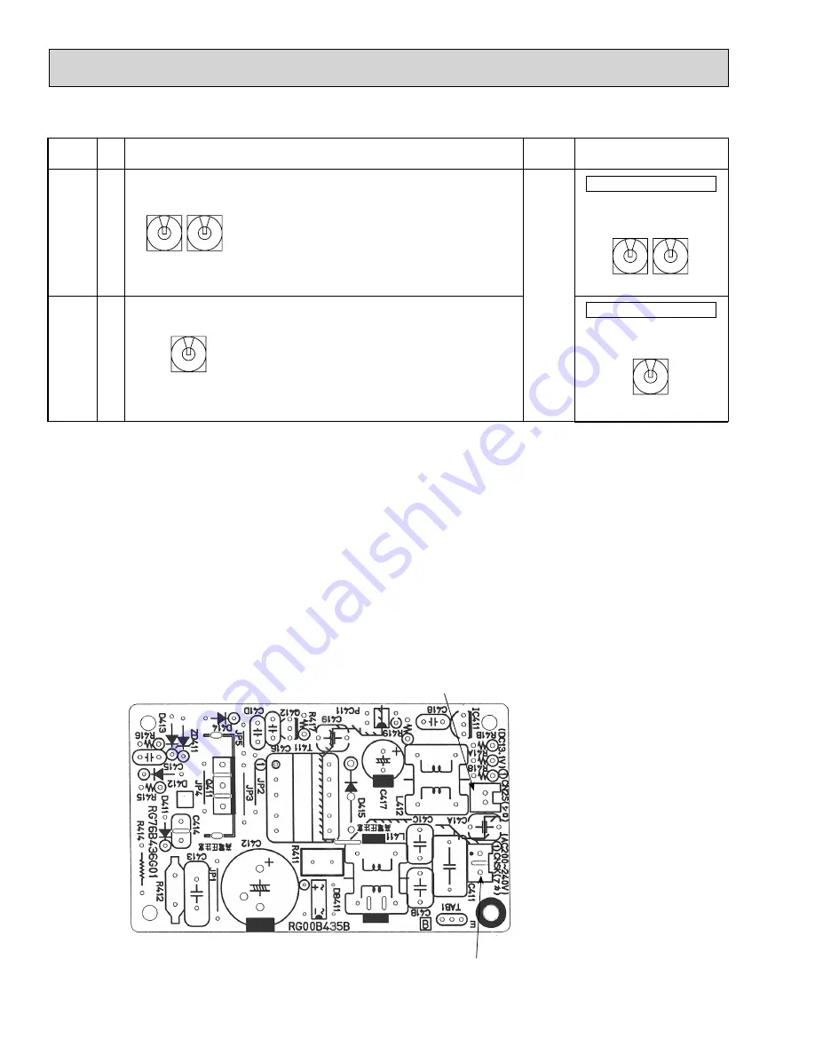
10-3-1. Indoor power board
PLFY-P08NCMU-E.TH PLFY-P12NCMU-E.TH PLFY-P15NCMU-E.TH
PLFY-P08NCMU-E
1
.TH PLFY-P12NCMU-E
1
.TH PLFY-P15NCMU-E
1
.TH
PLFY-P08NCMU-ER2.TH PLFY-P12NCMU-ER2.TH PLFY-P15NCMU-ER2.TH
CNSK
Connect to the indoor controller board (CNDK)
Between
1
to
3
208-230V AC
CN2S
Connect to the indoor controller board (CN2D)
Between
1
to
3
12.5-13.7V DC (Pin
1
(+))


