17
16
17
4
4-WAY AIR FLOW SYSTEM
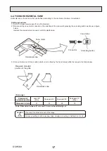
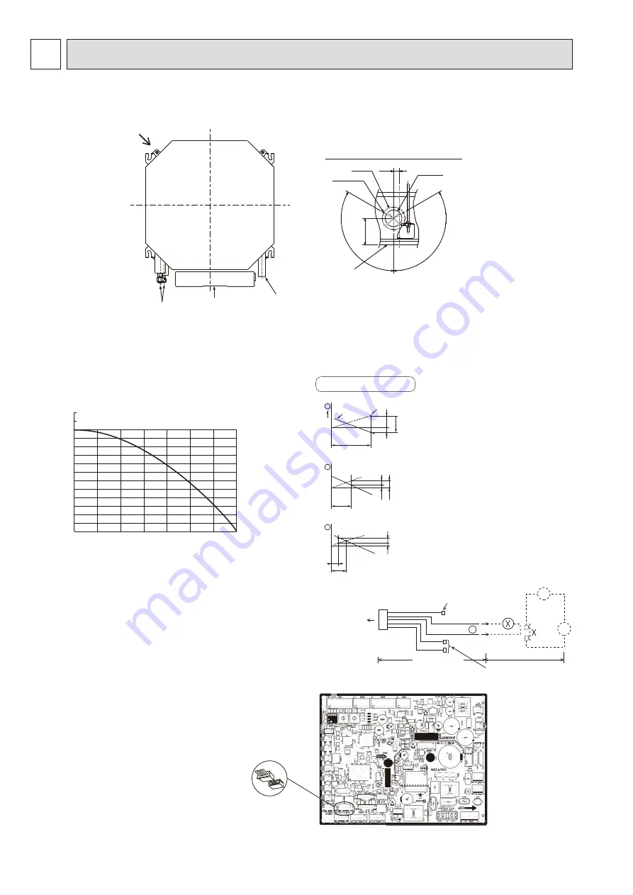
4-1. FRESH AIR INTAKE (Location for installation)
At the time of installation, use the duct holes (cut out) located at the positions shown in following diagram, as and when required.
Detail drawing of fresh air intake
Ceiling surface
Refrigerant pipe
Drain pipe
Electrical Box
Cut out hole
[
73.4
Burring hole
3-
[
2.8 hole
[
100
11
8
25
120°
120°
Fresh air intake
Static pressure : P [Pa]
Air flow : Q [m
3
/min]
50
-50
-100
-150
-200
-250
-300
0
0.5 1.0 1.5 2.0 2.5 3.0 3.5
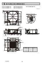
PLFY-P15VCM-E3.TH
PLFY-P20VCM-E3.TH
PLFY-P25VCM-E3.TH
PLFY-P32VCM-E3.TH PLFY-P40VCM-E3.TH
Taking air into the unit
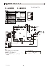
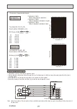
4-2. FRESH AIR INTAKE AMOUNT & STATIC PRESSURE CHARACTERISTICS
Q
0
B
A
C
1
Curve in the
left graphs
Duct characteristics
at site
Q
A
E
C
2
Q
Qa
A
D
3
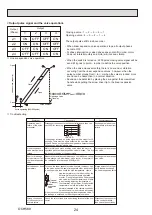
How to read curves
NOTE: Fresh air intake amount should be 20% or less of
whole air amount to prevent dew dripping.
Q…
Designed amount of fresh air intake
<m
3
/min>
A…
Static pressure loss of fresh air
intake duct system with air flow
amount Q
<Pa>
B…
Forced static pressure at air condi-
tioner inlet with air flow amount Q
<Pa>
C…
Static pressure of booster fan with
air flow amount Q
<Pa>
D…
Static pressure loss increase
amount of fresh air intake duct sys-
tem for air flow amount Q
<Pa>
E…
Static pressure of indoor unit with
air flow amount Q
<Pa>
Qa…
Estimated amount of fresh air
intake without D
<m
3
/min>
Multiple remote
controller adapter
PAC-SA88HA-E
Indoor controller board
Distance between indoor
controller board and relay
must be within 10m.
Be sure to secure insulation
material by tape, etc.
5
Green
Yellow
Orange
Connector (5P)
Indoor unit side
Multiple remote
controller adapter
PAC-SA88HA-E
Be sure to secure insulation
material by tape, etc.
Installation at site
CN51
on
indoor unit
board
Red
Brown
1
~
CN51
MB
+
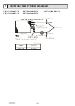
4-3. OPERATION IN CONJUNCTION
WITH DUCT FAN (Booster fan)
• Whenever the indoor unit operates, the duct fun also
operates.
(1) Connect the optional multiple remote controller
adapter(PAC-SA88HA-E) to the connector CN51 on
the indoor controller board.
(2) Drive the relay after connecting the 12V DC relay
between the Yellow and Orange connector wires.
MB: Electromagnetic switch power relay for duct fan.
X: Auxiliary relay
(For DC 12V, coil rating: 1.0W or below)
OCH569


