33
GB
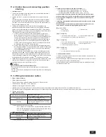
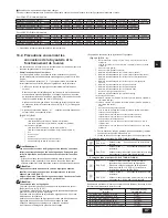
<Maximum Lengths>
1
ME Remote controller [Fig. 11.3.1] [Fig. 11.3.4] (P.15, 16)
Max length via heat source units: L
1
+L
2
+L
3
+L
4
and L
1
+L
2
+L
3
+L
5
and L
1
+L
2
+L
6
500 m [1,640 ft] (1.25 mm
2
>$:*@RUPRUH
Max transmission cable length: L
1
and L
3
+L
4
and L
3
+L
5
and L
6
and L
2
+L
6
200 m [656 ft] (1.25 mm
2
>$:*@RUPRUH
Remote controller cable length:
1
,
2
,
3
,
4
10 m [32 ft] (0.3 to 1.25 mm
2
>$:*WR@
If the length exceeds 10 m [32 ft], use a 1.25 mm
2
[AWG 16] shielded wire. The length of this section (L
8
VKRXOGEHLQFOXGHGLQWKH
calculation of the maximum length and overall length.
2
MA Remote controller [Fig. 11.3.2] [Fig. 11.3.5] (P.15, 17)
0D[OHQJWKYLDKHDWVRXUFHXQLW0(FDEOH/
1
+L
2
+L
3
+L
4
and L
1
+L
2
+L
6
500 m [1,640 ft] (1.25 mm
2
>$:*@RUPRUH
0D[WUDQVPLVVLRQFDEOHOHQJWK0(FDEOH/
1
and L
3
+L
4
and L
6
and L
2
+L
6
200 m [656 ft] (1.25 mm
2
>$:*@RUPRUH
Remote controller cable length:
m
1
+
m
2
and
m
1
+
m
2
+
m
3
+
m
4
200 m [656 ft] (0.3 to 1.25 mm
2
>$:*WR@
3
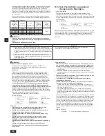
Transmission booster [Fig. 11.3.3] [Fig. 11.3.6] (P.16, 17)
0D[WUDQVPLVVLRQFDEOHOHQJWK0(FDEOH
For PQHY
1
L
11
+ L
12
+ L
13
+ L
15
+ L
16
200 m [656 ft] (1.25 mm
2
>$:*@
2
L
11
+ L
12
+ L
13
+ L
15
+ L
17
200 m [656 ft] (1.25 mm
2
>$:*@
3
L
11
+ L
12
+ L
14
200 m [656 ft] (1.25 mm
2
>$:*@
4
L
16
+ L
15
+ L
13
+ L
14
, L
14
+ L
13
+ L
15
+ L
17
200 m [656 ft] (1.25 mm
2
>$:*@
For PQRY
1
L
11
+ L
12
+ L
13
+ L
14
+ L
16
+ L
17
200 m [656 ft] (1.25 mm
2
>$:*@
2
L
11
+ L
12
+ L
13
+ L
14
+ L
16
+ L
18
200 m [656 ft] (1.25 mm
2
>$:*@
3
L
11
+ L
12
+ L
13
+ L
15
200 m [656 ft] (1.25 mm
2
>$:*@
4
L
17
+ L
16
+ L
14
+ L
15
, L
15
+ L
14
+ L
16
+ L
18
200 m [656 ft] (1.25 mm
2
>$:*@
Remote controller cable length:
1
,
2
10 m [32 ft] (0.3 to 1.25 mm
2
>$:*WR@
If the length exceeds 10 m [32 ft], use 1.25 mm
2
[AWG 16] shielded cable and calculate the length of that portion (L
15
and L
18
DV
within the total extended length and the longest remote length.
11.4. Wiring of main power supply and equipment capacity
Schematic Drawing of Wiring (Example)
[Fig. 11.4.1] (P.17)
A
6ZLWFK%UHDNHUVIRUZLULQJDQGFXUUHQWOHDNDJH
B
Breakers for current leakage
C
Heat source unit
D
Pull box
E
Indoor unit
F
%&FRQWUROOHUVWDQGDUGRUPDLQIRU345<3ā76/08$<6/08$
F
'
%&FRQWUROOHUVXEIRU345<3ā76/08$<6/08$
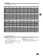
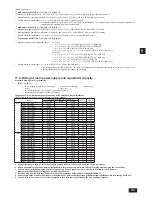
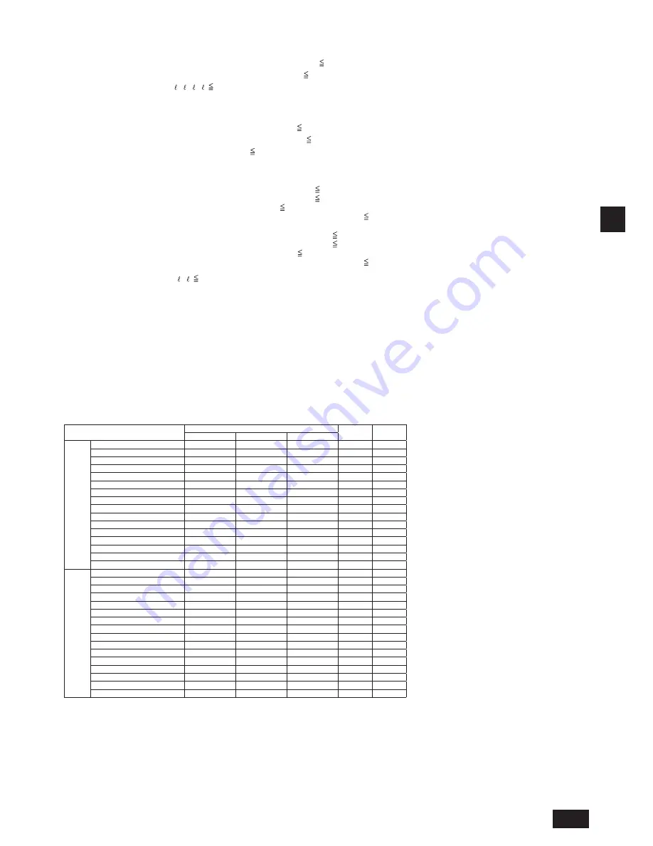
Thickness of wire for main power supply, capacities of the switch and system impedance
MOP is used to select the fuse, switch, or breaker for current leakage.
Model
Minimum wire thickness (mm
2
>$:*@
0&$$
023$
Main cable
Branch
Ground
WY
PQHY-P72TLMU-A
3.3[12]
-
3.3[12]
13
20
PQHY-P96TLMU-A
5.3[10]
-
5.3[10]
19
30
PQHY-P120TLMU-A
8.4[8]
-
8.4[8]
29
50
PQHY-P144TLMU-A
13.3[6]
-
13.3[6]
35
60
PQHY-P168TLMU-A
13.3[6]
-
13.3[6]
44
70
PQHY-P192TLMU-A
21.2[4]
-
21.2[4]
54
90
PQHY-P216TLMU-A
33.6[2]
-
33.6[2]
69
110
PQHY-P240TLMU-A
33.6[2]
-
33.6[2]
79
125
PQHY-P72YLMU-A
2.1[14]
-
2.1[14]
6
15
PQHY-P96YLMU-A
2.1[14]
-
2.1[14]
9
15
PQHY-P120YLMU-A
3.3[12]
-
3.3[12]
13
20
PQHY-P144YLMU-A
3.3[12]
-
3.3[12]
16
25
PQHY-P168YLMU-A
5.3[10]
-
5.3[10]
20
35
PQHY-P192YLMU-A
5.3[10]
-
5.3[10]
25
40
PQHY-P216YLMU-A
8.4[8]
-
8.4[8]
31
50
PQHY-P240YLMU-A
13.3[6]
-
13.3[6]
36
60
WR2
PQRY-P72TLMU-A
3.3[12]
-
3.3[12]
13
20
PQRY-P96TLMU-A
5.3[10]
-
5.3[10]
19
30
PQRY-P120TLMU-A
8.4[8]
-
8.4[8]
29
50
PQRY-P144TLMU-A
13.3[6]
-
13.3[6]
35
60
PQRY-P168TLMU-A
13.3[6]
-
13.3[6]
44
70
PQRY-P192TLMU-A
21.2[4]
-
21.2[4]
54
90
PQRY-P216TLMU-A
33.6[2]
-
33.6[2]
69
110
PQRY-P240TLMU-A
33.6[2]
-
33.6[2]
79
125
PQRY-P72YLMU-A
2.1[14]
-
2.1[14]
6
15
PQRY-P96YLMU-A
2.1[14]
-
2.1[14]
9
15
PQRY-P120YLMU-A
3.3[12]
-
3.3[12]
13
20
PQRY-P144YLMU-A
3.3[12]
-
3.3[12]
16
25
PQRY-P168YLMU-A
5.3[10]
-
5.3[10]
20
35
PQRY-P192YLMU-A
5.3[10]
-
5.3[10]
25
40
PQRY-P216YLMU-A
8.4[8]
-
8.4[8]
31
50
PQRY-P240YLMU-A
13.3[6]
-
13.3[6]
36
60
1. Use dedicated power supplies for the heat source unit and indoor unit. Ensure OC and OS are wired individually.
2. Bear in mind ambient conditions (ambient temperature, direct sunlight, rain water, etc.) when proceeding with the wiring and connections.
3. The wire size is the minimum value for metal conduit wiring. If the voltage drops, use a wire that is one rank thicker in diameter.
Make sure the power-supply voltage does not drop more than 10%.
6SHFL¿FZLULQJUHTXLUHPHQWVVKRXOGDGKHUHWRWKHZLULQJUHJXODWLRQVRIWKH&6$DQG$16,1)3$1R
3RZHUVXSSO\FRUGVRISDUWVRIDSSOLDQFHVIRUKHDWVRXUFHXVHVKDOOQRWEHOLJKWHUWKDQSRO\FKORURSUHQHVKHDWKHGÀH[LEOHFRUGGHVLJQ,(&
6. A switch with at least 3 mm [1/8in] contact separation in each pole shall be provided by the Air Conditioner installer.
Summary of Contents for CITY MULTI PQHY-P-TLMU-A
Page 55: ......


