
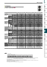


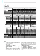
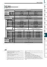


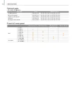


JA1 type
CMB-M V-JA1
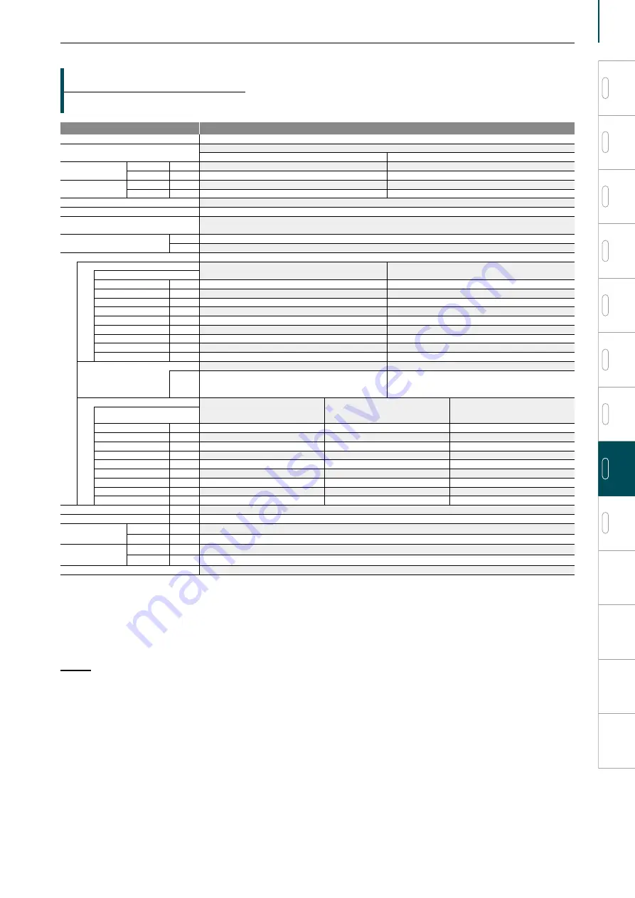
Model
CMB-M1016V-JA1
Number of branch
16
Power source
1-phase 220-230-240 V
50 Hz
60 Hz
Power input
(220/230/240)
Cooling
kW
0.246/0.279/0.312
0.198/0.222/0.246
Heating
kW
0.119/0.135/0.151
0.096/0.108/0.119
Current input
(220/230/240)
Cooling
A
1.12/1.22/1.30
0.90/0.97/1.03
Heating
A
0.55/0.59/0.63
0.44/0.47/0.50
External finish
Galvanized steel plate (Lower part drain pan: Pre-coated galvanized powder coating)
Connectable outdoor/heat source unit capacity
P200 to P900
Indoor unit capacity
connectable to 1 branch *13
Model P80 or smaller
(Use optional joint pipe combining 2 branches when the total unit capacity exceeds P81.)
External dimension HxWxD
mm
252 x 1,135 x 622
in.
9-15/16 x 44-11/16 x 24-1/2
Refrigerant piping diameter
To outdoor/heat source unit
High press. pipe
Low press. pipe
Connectable unit capacity
P200
mm(in.) O.D.
15.88 (5/8) Brazed
19.05 (3/4) Brazed
P250/P300
mm(in.) O.D.
19.05 (3/4) Brazed
22.2 (7/8) Brazed
P350 *14
mm(in.) O.D.
19.05 (3/4) Brazed or 22.2 (7/8) Brazed
28.58 (1-1/8) Brazed
P400 to P500
mm(in.) O.D.
22.2 (7/8) Brazed
28.58 (1-1/8) Brazed
P550 *14
mm(in.) O.D.
22.2 (7/8) Brazed or 28.58 (1-1/8) Brazed
28.58 (1-1/8) Brazed
P600 *14
mm(in.) O.D.
22.2 (7/8) Brazed or 28.58 (1-1/8) Brazed
28.58 (1-1/8) Brazed or 34.93 (1-3/8) Brazed
P650
mm(in.) O.D.
28.58 (1-1/8) Brazed
28.58 (1-1/8) Brazed
P700 to P800
mm(in.) O.D.
28.58 (1-1/8) Brazed
34.93 (1-3/8) Brazed
P850 to P900
mm(in.) O.D.
28.58 (1-1/8) Brazed
41.28(1-5/8) Brazed
To indoor unit
Liquid pipe
Gas pipe
mm(in.) O.D.
Indoor unit Model 50 or smaller 6.35 (1/4) Brazed
bigger than 50 9.52 (3/8) Brazed
Indoor unit Model 50 or smaller 12.7 (1/2) Brazed
bigger than 50 15.88 (5/8) Brazed
(19.05 (3/4), 22.2 (7/8) with optional joint pipe used.)
To other BC controller
High press. pipe
Liquid pipe
Low press. pipe
Total down-stream Indoor unit
capacity
to P200
mm(in.) O.D.
15.88 (5/8) Brazed
9.52 (3/8) Brazed
19.05 (3/4) Brazed
P201 to P300
mm(in.) O.D.
19.05 (3/4) Brazed
9.52 (3/8) Brazed
22.2 (7/8) Brazed
P301 to P350
mm(in.) O.D.
19.05 (3/4) Brazed
12.7 (1/2) Brazed
28.58 (1-1/8) Brazed
P351 to P400
mm(in.) O.D.
22.2 (7/8) Brazed
12.7 (1/2) Brazed
28.58 (1-1/8) Brazed
P401 to P600
mm(in.) O.D.
22.2 (7/8) Brazed
15.88 (5/8) Brazed
28.58 (1-1/8) Brazed
P601 to P650
mm(in.) O.D.
28.58 (1-1/8) Brazed
15.88 (5/8) Brazed
28.58 (1-1/8) Brazed
P651 to P800
mm(in.) O.D.
28.58 (1-1/8) Brazed
19.05 (3/4) Brazed
34.93 (1-3/8) Brazed
P801 to P1000
mm(in.) O.D.
28.58 (1-1/8) Brazed
19.05 (3/4) Brazed
41.28(1-5/8) Brazed
P1001 or above
mm(in.) O.D.
34.93 (1-3/8) Brazed
19.05 (3/4) Brazed
41.28(1-5/8) Brazed
Field drain pipe size
mm (in.)
O.D. 32 (1-1/4)
Net weight
kg (lbs)
68 (150)
Sound power level
(measured in anechoic
room)
Rated operation dB <A>
68
Defrost
dB <A>
74
Sound pressure level
(measured in anechoic
room) *15
Rated operation dB <A>
50
Defrost
dB <A>
56
Accessories
Drain Connection pipe, Washer, Tie band
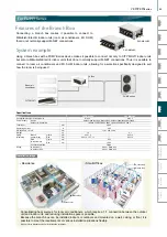
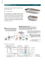
1.Installation/foundation work, electrical connection work, insulation work, power source
switch, and other items shall be referred to the Installation Manual.
2.The equipment is for R410A refrigerant.
3.Install this product in a location where noise (refrigerant noise) emitted by the unit will
not disturb the neighbors.
(For use in quiet environments with low background noise, position the BC
CONTROLLER at least 5m away from any indoor units.)
4.Sound pressure/power level differs depending on the connected outdoor/heat source
unit capacity or operation condition.
The sound pressure/power level at the rated operation is the value of the cooling
mode.
5.The sound pressure/power level values were obtained in an anechoic room. Actual
sound pressure level is usually greater than that measured in anechoic room due to
ambient noise and deflection sound.
6.The sound pressure level values were obtained at the location below 1.5m from the
unit.
7.The solenoid valve switching sound is 56 dB (sound pressure level) regardless of the unit
model.
8.Indoor units P100, P125, P140 can be connected to 1 branch. (In this case, cooling
capacity decrease a little.)
9.Refrigerant piping diameter for connection of plural indoor units with 1 branch shall be
referred to the Installation Manual.
10.This unit is not designed for outside installations.
11.When brazing the pipes, be sure to braze after covering a wet cloth to the insulation pipes
of the units in order to prevent it from burning and shrinking by heat.
12.The ambient relative humidity of the BC controller needs to be kept below 80%.
13.Indoor unit capacity connectable to 1 branch is changed depending on the indoor unit type
and connection method. Please refer to the Installation Manual for more information.
14.For the refrigerant pipe size, refer to Installation Manual of outdoor units/heat source units.
15.The sound pressure level measured by the conventional method in JIS for reference
purpose.
Notes:
VRF
Y-Series
VRF
Lineup
VRF
R2-Series
VRF
Zubadan
VRF
WY-Series
VRF
WR2-Series
VRF
S-Series
VRF
Indoor Units
Ventilation
Systems
Technologies and Functions
Remote Controller
Hot Water Solution
VRF
BC Controllers
VRF
S-Series
109
SPECIFICATIONS
Summary of Contents for City Multi R2 Series
Page 1: ...CM20AN E NZ VRF City Multi Product Catalogue ...
Page 101: ...BC Controllers 101 ...
Page 112: ...Indoor Units VRF 112 ...
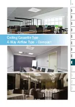
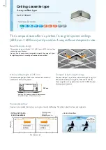
Page 114: ...Ceiling Cassette Type 4 Way Airflow Type 114 ...
Page 122: ...Ceiling Cassette Type 2 Way Airflow Type 122 ...
Page 128: ...Ceiling Concealed Type 128 ...
Page 150: ...Wall Mounted Type 150 ...
Page 154: ...Floor Standing Type 154 ...
Page 181: ...Ventilation Systems 181 ...
Page 190: ...Remote Controllers 190 ...


