
The following tables are applicable when using equipment under the conditions below.
Normal use without frequent START/STOPs (The number of START/STOPs is assumed to be less than 6 times
per hour in normal use.)
Operating hours are assumed to be 10 hours per day/2500 hours per year.
When the equipment is used under the following conditions, the "maintenance cycle" and "replacement intervals"
may be shortened.
When equipment is used in an environment where the temperature and humidity are high or change dramatically
When equipment is used in an environment where power supply fluctuations (the distortion of voltage,
frequency, and waveform) are large (Only within the allowable range)
When equipment is used in an environment where the unit may receive vibration or mechanical shock
When equipment is used in an environment where dust, salt, toxic gases such as sulfur dioxide and hydrogen
sulfide, and oil mist are present
When equipment starts/stops frequently and operates for long periods (24-hour air-conditioning operation)
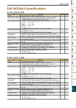
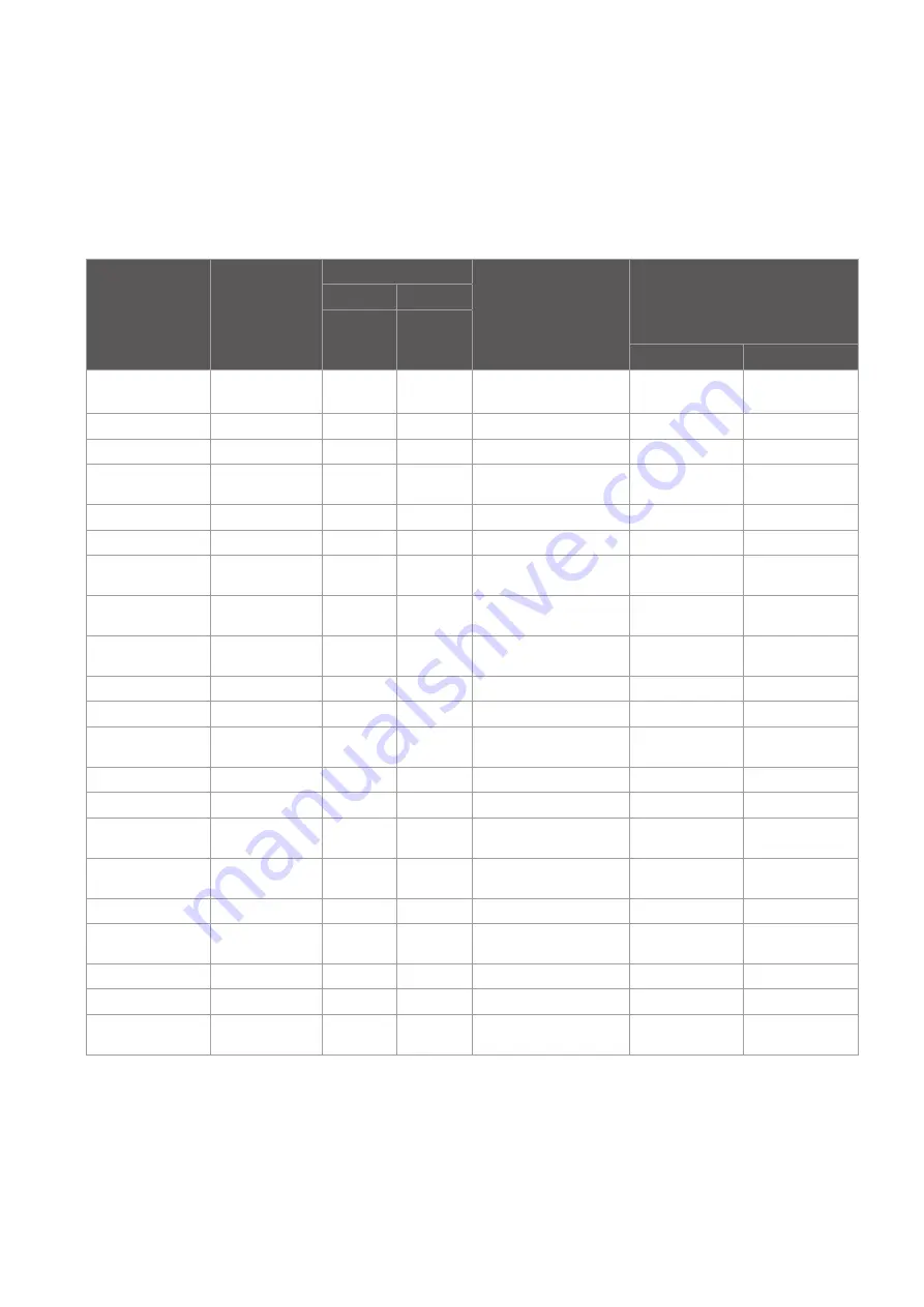
Table 1. Maintenance cycle
Table 2. Replacement cycle
Major components
Checking cycle
Maintenance cycle
Compressor
20,000 hours
Motor
20,000 hours
(Fan, louver, drain pump)
Bearings
1 year
15,000 hours
Electric board
25,000 hours
Heat exchanger
5 years
Major components
Checking cycle
Maintenance cycle
Expansion valve
20,000 hours
Valve
20,000 hours
(solenoid valve, four-way valve)
1 year
Sensor
5 years
(thermistor, pressure sensor)
Drain pan
8 years
Major components
Checking cycle
Replacement cycle
Long-life filter
5 years
High-performance filter
1 year
Fan belt
1 year
5,000 hours
Smoothing capacitor
10 years
Fuse
10 years
Crank case heater
8 years
Note 1 This table shows major components. Refer to the maintenance contract for details.
Note 2 This maintenance cycle shows a period in which products are expected to require no maintenance. Use this cycle for planning maintenance (budgeting the
maintenance expense etc.) The Checking/ Maintenance cycle may be shorter than the one shown on this table depending on the contents of the
maintenance check contract.
M
aintenance Equipment
Maintenance cycle
[Note that maintenance cycle does not mean guarantee period.]
Replacement cycle for consumable components
[Note that replacement cycle does not mean guarantee period.]
Sudden unpredictable accidents may occur even if check-ups are performed.
Note 1 This table shows major components. Refer to the maintenance contract
for details.
Note 2 This replacement cycle shows a period in which products are expected to
require no replacement. Use this cycle for planning maintenance
(budgeting expenses for replacing equipment, etc.)
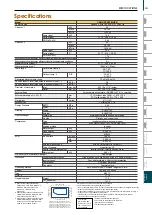
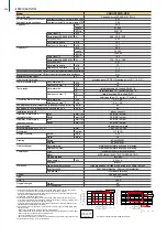
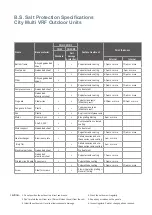
B.S. Salt Protection Specifications
City Multi VRF Outdoor Units
Name
Base material
PUHY, PURY
Surface treatment
Paint thickness
YNW
YNW-BS
Standard
Salt
damage
protection
External
Internal
Bottom frame
Alloyed galvanized
sheet
•
•
Polyester resin coating
70μm or more
70μm or more
Front panel
Galvanized sheet
•
Polyester resin coating
15μm or more
5μm or more
•
Polyester resin coating
85μm or more
75μm or more
Pillar
Alloyed galvanized
sheet
•
Polyester resin coating
30μm or more
•
Polyester resin coating
70μm or more
70μm or more
Compressor cover
Galvanized sheet
•
No treatment
Galvanized
aluminum sheet
•
Polyester resin coating
70μm or more
70μm or more
Fin guard
Steel wires
•
•
Polyethylene resin
(Weather proof)
300μm or more
300μm or more
Fan guard & Drum
Plastic
•
•
Polypropylene resin
(Weather proof)
Fan
Plastic
•
•
Acrylics nitril styrene resin
Motor
Frame; Spcc
•
•
Zinc plating filming
8μm or more
Shaft; S35C
•
•
Rust prevention coloured
coating
Motor support
Galvanized sheet
•
No treatment
•
Polyester resin coating
70μm or more
70μm or more
Heat exchanger
Aluminum plate
•
Cellulose series and ure-
thane series resin coating
1μm or more
(Only fin)
•
Cellulose series and ure-
thane series resin coating
3μm or more
Electrical parts box
Galvanized sheet
•
No treatment
Galvanized
aluminum sheet
•
Polyester resin coating
70μm or more
Printed circuit board Epoxy resin
•
Polyurethane coating
10μm or more
•
Polyurethane coating
10μm or more
10μm or more
Screw
Steel for screws
•
•
Zinc-nickel alloy p
Geomet filming
1 Do not position the outdoor in a direct sea breeze.
2 Don’t protect the unit from rain. (Rain will clean the salt from the coil).
3 Install the outdoor unit level to allow condensate drainage.
CAUTION:
4 Wash the outdoor unit regularly.
5 Repair any scratches on the panels.
6 Inspect regularly. Paint or change parts as required.
Summary of Contents for City Multi R2 Series
Page 1: ...CM20AN E NZ VRF City Multi Product Catalogue ...
Page 101: ...BC Controllers 101 ...
Page 112: ...Indoor Units VRF 112 ...
Page 114: ...Ceiling Cassette Type 4 Way Airflow Type 114 ...
Page 122: ...Ceiling Cassette Type 2 Way Airflow Type 122 ...
Page 128: ...Ceiling Concealed Type 128 ...
Page 150: ...Wall Mounted Type 150 ...
Page 154: ...Floor Standing Type 154 ...
Page 181: ...Ventilation Systems 181 ...
Page 190: ...Remote Controllers 190 ...


