


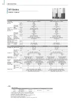

WY
-Series
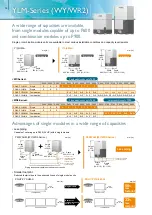
• System pipe lengths
[P200-P900]
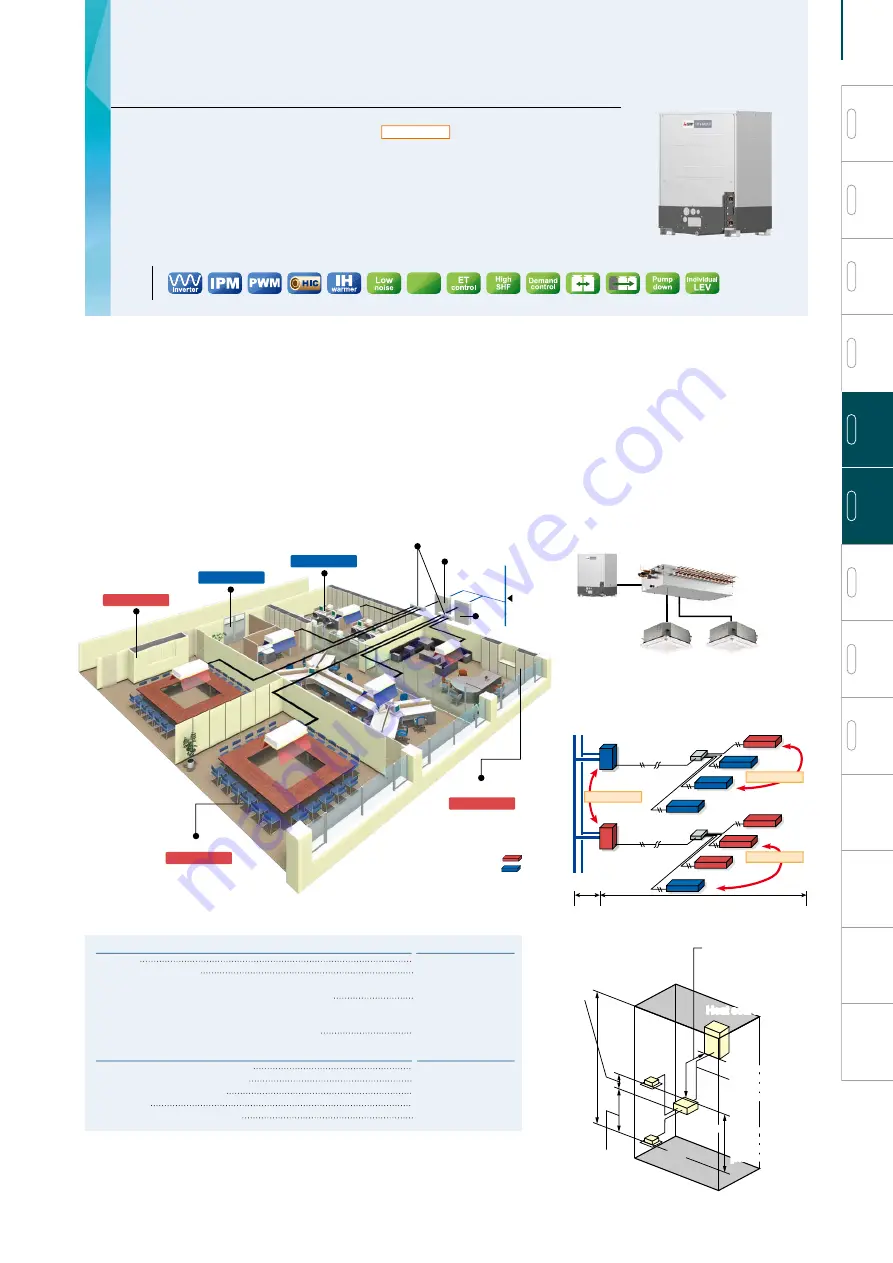
• Installation image (WY-Series)
Director's room
Heat source unit
Meeting room
Meeting room
Office area
Water piping
Heat
source
unit
Office area
Cooling
Cooling
Cooling
Cooling
Cooling
Heat source unit
Heat source unit
Indoor unit
Between indoor units
top-bottom differential
15m [49ft]
Between indoor units
top-bottom differential
15m [49ft]
Top-bottom
differential
50m [164ft]*1
Top-bottom
differential
50m [164ft]*1
Furthest piping length
190m [623ft]
(equivalent length)
(actual length 165m [541ft])
Furthest piping length
190m [623ft]
(equivalent length)
(actual length 165m [541ft])
*1 When the heat source unit is installed below the indoor unit, top-bottom differential is 40m [131ft].
*2 90m [295ft] is available. When the piping length exceeds 40m [131ft], use one size larger liquid pipe starting with the section of piping where 40m [131ft] is exceeded and all
piping after that point.
Refrigerant piping lengths
Total length
Maximum allowable length
Furthest indoor unit from first branch
Vertical differentials between units
Indoor/heat source (heat source higher)
Indoor/heat source (heat source lower)
Indoor/indoor
Maximum meters [Feet]
300-500 [984-1640]
165 (190 equivalent)
[541(623)]
40 [131]*2
Maximum meters [Feet]
50 [164]
40 [131]
15 [49]
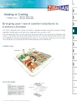
Cooling or Heating
Heat pump
• Features ∙∙∙∙∙∙∙∙∙∙∙∙∙∙∙∙∙∙∙∙∙∙∙∙∙∙∙∙∙∙∙∙∙∙∙∙∙∙∙∙∙∙∙∙∙∙∙∙∙∙∙∙∙∙∙∙∙∙∙∙∙∙∙∙∙∙∙∙∙∙∙∙∙∙∙∙∙∙∙∙∙∙∙∙∙∙∙∙∙∙∙∙∙∙∙∙∙∙
P.70, P.72 - P.73
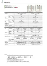
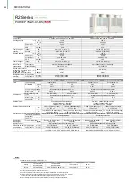
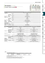
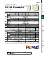
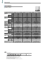
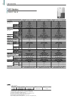
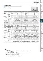
• Specifications
PQHY-P Y(S)LM-A1
∙∙∙∙∙∙∙∙∙∙∙∙∙∙∙∙∙∙∙∙∙∙∙∙∙∙∙∙∙∙∙∙∙∙∙∙∙∙∙∙∙∙∙∙∙∙∙∙∙∙∙∙∙∙∙∙∙∙∙∙∙∙
P.74 - P.80
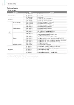
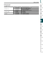
• Optional parts ∙∙∙∙∙∙∙∙∙∙∙∙∙∙∙∙∙∙∙∙∙∙∙∙∙∙∙∙∙∙∙∙∙∙∙∙∙∙∙∙∙∙∙∙∙∙∙∙∙∙∙∙∙∙∙∙∙∙∙∙∙∙∙∙∙∙∙∙∙∙∙∙∙∙∙∙∙∙∙∙∙∙∙∙∙∙∙∙∙∙∙∙∙∙∙∙∙∙∙∙∙∙∙∙∙∙
P.81
• Technologies and functions
∙∙∙∙∙∙∙∙∙∙∙∙∙∙∙∙∙∙∙∙∙∙∙∙∙∙∙∙∙∙∙∙∙∙∙∙∙∙∙∙∙∙∙∙∙∙∙∙∙∙∙∙∙∙∙∙∙∙∙∙∙∙∙∙∙∙∙∙∙∙∙∙∙∙∙∙∙∙∙∙∙∙∙∙∙∙∙∙∙∙∙∙∙∙∙∙P.162
A water energy source system that allows switching
between cooling and heating
The CITY MULTI WY-Series provides all the benefits of the Y-Series using water-cooled heat source units.
Heat source units can be situated indoors for greater design flexibility with no limitations on building size. Depending on
capacity, up to 50 indoor units can be connected to a single heat source unit with individualized and/or centralized
control. The two-pipe system allows all CITY MULTI units to switch between cooling and heating while maintaining a
constant indoor temperature.
SCO
Dual
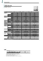
WR2
-Series
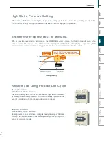
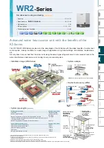
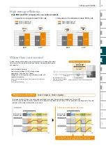
• Installation image (WR2-Series)
• System example
BC controller (required)*
• System pipe lengths
[P200-P900]
Advanced water heat source unit with the benefits of the
R2-Series
The CITY MULTI WR2-Series provides all of the advantages of the R2-Series with the added benefits of a water heat
source system, making it suitable for a wider range of applications in high-rise buildings, cold climates, coastal areas,
etc.
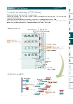
Not only does it recover heat from the indoor units along the same 2-pipe refrigerant circuit, it also recovers heat via the
water circuit between heat source units, making it a very economical system.
Cooling
Director's room
Heat source unit
BC controller
Meeting room
Office area
Cooling
Office area
Water
piping
Heat
source
unit
Meeting room
Heating
Heating
Heating
Heat source unit
Heat source unit
Between indoor unit
and BC controller
top-bottom differential 15m (10m)
[49ft (32ft)] *4
Between indoor unit
and BC controller
top-bottom differential 15m (10m)
[49ft (32ft)] *4
Top-bottom
differentrial
50m [164ft] *1
Top-bottom
differentrial
50m [164ft] *1
Furthest piping length
190m [623ft]
(equivalent length)
(actual length 165m
[541ft])
Furthest piping length
190m [623ft]
(equivalent length)
(actual length 165m
[541ft])
Indoor unit
Indoor unit
Maximum length
between heat source
and single/main
BC controller
110m [360ft] *2
Maximum length
between heat source
and single/main
BC controller
110m [360ft] *2
BC
controller
BC
controller
Between indoor unit and
BC controller top-
bottom differential
15m (10m)
[49ft (32ft)] *4
Between indoor unit and
BC controller top-
bottom differential
15m (10m)
[49ft (32ft)] *4
Between indoor units
top-bottom
differential 30m (20m)
[98ft (65ft)] *5
Between indoor units
top-bottom
differential 30m (20m)
[98ft (65ft)] *5
*1 When the heat source unit is installed below the indoor unit, top-bottom differential is 40m [131ft].
*2 Details refer to the DATA BOOK.
*3 Farthest Indoor from BC controller can exceed 40m [131ft.] till 60m [197ft.] if no Indoor sized P200, P250 connected.
Details refer to the DATA BOOK.
*4 Distance of Indoor sized P200, P250 from BC must be less than 10m [32 ft.], if any.
*5 Distance of Indoor sized P200, P250 from indoor unit must be less than 20m [65 ft.], if any.
*6 Distance between BC (Main) and BC (Sub) must be less than 10m [32 ft.], if two BC (Sub) are installed or Indoor sized P200 and/or P250 is connected.
Simultaneous Cooling and Heating
Heat recovery
Refrigerant piping lengths
Total length
Maximum allowable length
Maximum length between heat source and single/main BC controller
*Maximum total length is dependent upon the distance between the outdoor unit and
the single/main BC controller.
Maximum length between single/main BC controller and indoor
Vertical differentials between units
Indoor/ heat source (heat source higher)
Indoor/ heat source (heat source lower)
Indoor/BC controller (single/main)
Indoor/indoor
Main BC controller/Sub BC controller
Maximum meters [Feet]
550-750 [1,804-2,460]
165 (190 equivalent)
[541 (623)]
110 [360]*2
40 [131]*3
Maximum meters [Feet]
50 [164]
40 [131]
15 [49]*4
30 [98]*5
15 [49]*6
• Features ∙∙∙∙∙∙∙∙∙∙∙∙∙∙∙∙∙∙∙∙∙∙∙∙∙∙∙∙∙∙∙∙∙∙∙∙∙∙∙∙∙∙∙∙∙∙∙∙∙∙∙∙∙∙∙∙∙∙∙∙∙∙∙∙∙∙∙∙∙∙∙∙∙∙∙∙∙∙∙∙∙∙∙∙∙∙∙∙∙∙∙∙∙∙∙∙∙∙∙∙∙∙∙∙∙∙
P.70 - P.73
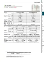
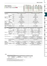
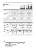
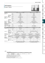
• Specifications
PQRY-P Y(S)LM-A1
∙∙∙∙∙∙∙∙∙∙∙∙∙∙∙∙∙∙∙∙∙∙∙∙∙∙∙∙∙∙∙∙∙∙∙∙∙∙∙∙∙∙∙∙∙∙∙∙∙∙∙∙∙∙∙∙∙∙∙∙∙∙
P.82 - P.89
• Optional parts ∙∙∙∙∙∙∙∙∙∙∙∙∙∙∙∙∙∙∙∙∙∙∙∙∙∙∙∙∙∙∙∙∙∙∙∙∙∙∙∙∙∙∙∙∙∙∙∙∙∙∙∙∙∙∙∙∙∙∙∙∙∙∙∙∙∙∙∙∙∙∙∙∙∙∙∙∙∙∙∙∙∙∙∙∙∙∙∙∙∙∙∙∙∙∙∙∙∙∙∙∙∙∙∙∙∙
P.90
• BC controllers ∙∙∙∙∙∙∙∙∙∙∙∙∙∙∙∙∙∙∙∙∙∙∙∙∙∙∙∙∙∙∙∙∙∙∙∙∙∙∙∙∙∙∙∙∙∙∙∙∙∙∙∙∙∙∙∙∙∙∙∙∙∙∙∙∙∙∙∙∙∙∙∙∙∙∙∙∙∙∙∙∙∙∙∙∙∙∙∙∙∙∙∙∙∙
P.101 - P.111
• Technologies and functions
∙∙∙∙∙∙∙∙∙∙∙∙∙∙∙∙∙∙∙∙∙∙∙∙∙∙∙∙∙∙∙∙∙∙∙∙∙∙∙∙∙∙∙∙∙∙∙∙∙∙∙∙∙∙∙∙∙∙∙∙∙∙∙∙∙∙∙∙∙∙∙∙∙∙∙∙∙∙∙∙∙∙∙∙∙∙∙∙∙∙∙∙∙∙∙∙P.162
*WR2-Series systems require the use of BC controllers.
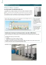
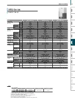
• Double heat recovery (WR2)
Indoor units
Indoor units
Heat source unit
BC controller
Heat recovery
Heat recovery
Heat recovery
Water
circuit
Heating
Cooling
Refrigerant circuit
Dual
69
VRF
Lineup
VRF
R2-Series
VRF
Zubadan
VRF
WY-Series
VRF
WR2-Series
VRF
S-Series
VRF
Indoor Units
Ventilation
Systems
Technologies and Functions
Remote Controller
Hot Water Solution
VRF
BC Controllers
VRF
S-Series
VRF
Y-Series
Summary of Contents for City Multi R2 Series
Page 1: ...CM20AN E NZ VRF City Multi Product Catalogue ...
Page 101: ...BC Controllers 101 ...
Page 112: ...Indoor Units VRF 112 ...
Page 114: ...Ceiling Cassette Type 4 Way Airflow Type 114 ...
Page 122: ...Ceiling Cassette Type 2 Way Airflow Type 122 ...
Page 128: ...Ceiling Concealed Type 128 ...
Page 150: ...Wall Mounted Type 150 ...
Page 154: ...Floor Standing Type 154 ...
Page 181: ...Ventilation Systems 181 ...
Page 190: ...Remote Controllers 190 ...


