


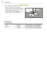


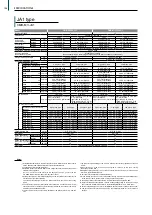

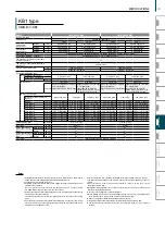
Precautions for system design
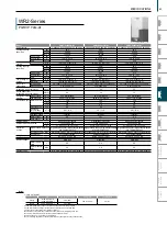
Comparison of Piping Lengths for PUMY-Series Models
Mixed System
(City Multi
*1
Indoor Unit + Branch Box)
*1 Include system with connection kit
*2 Farthest branch box from first branch.
*3 In case of including PKFY or PFFY, height between units is 30m.
*4 In case of branch box connection : 12m
*5 Liquid pipe diameter: 12.7 mm, in case of further piping length is longer than 60 m, or the farthest length of main pipe between outdoor unit and branch box is longer than 20 m in branch box system.
*6 Use liquid pipe of ø9.52 for less than P50 indoor units, when farthest length from the first joint exceeds 30m.
150
80
30
*2
95
25
55
55
15
15
80
*5
30
*2
95
25
55
55
*5
15
15
80
50
*2 *6
95
25
55
55
15
15
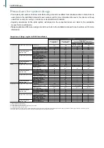
Total Length
Maximum Allowable Length
Farthest Indoor From First Branch
Indoor/Outdoor(Outdoor higher)
Indoor/Outdoor(Outdoor lower)
Indoor/Indoor
Total branch pipe length
Farthest branch pipe length
Total main pipe length
Farthest main pipe length
Branch box/Indoor
Branch box/Branch box
Total Length
Maximum Allowable Length
Farthest Indoor
From First Branch
Indoor/Outdoor(Outdoor higher)
Indoor/Outdoor(Outdoor Lower)
Indoor/Indoor
Total branch pipe length
Farthest branch pipe length
Total main pipe length
Farthest main pipe length
Branch box/Indoor
Branch box/Branch box
Total Length
Maximum Allowable Length
Farthest Indoor
From First Branch
Indoor/Outdoor(Outdoor higher)
Indoor/Outdoor(Outdoor Lower)
Indoor/Indoor
Total branch pipe length
Farthest branch pipe length
Total main pipe length
Farthest main pipe length
Branch box/Indoor
Branch box/Branch box
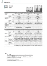
Refrigerant Piping Length
Vertical Differentials
Between Units
Refrigerant Piping Length
Vertical Differentials
Between Units
Refrigerant Piping Length
Vertical Differentials
Between Units
Refrigerant Piping Length
Vertical Differentials
Between Units
Refrigerant Piping Length
Vertical Differentials
Between Units
Refrigerant Piping Length
Vertical Differentials
Between Units
P112/125/140
P200
SP80/112/125/145
300
150 (175 equivalent)
30
50
40
15
-
-
-
-
-
-
150
80 (90 equivalent)
*5
30
50
40
15
―
―
―
―
―
―
120
70 (90 equivalent)
50
*6
50
30
15
―
―
―
―
―
―
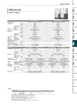
150
80
30
*2
50
40
15
*4
95
25
55
55
15
15
150
80
*5
30
*2
50
40
15
*4
95
25
55
55
*5
15
15
120
80
50
*2
50
30
15
*4
95
25
55
55
15
15
300 (with 1 branch box)
240 (with 2 branch boxes)
85
30
-
-
-
-
-
-
80 (90 equivalent)
*5
30
―
―
―
―
―
―
70 (90 equivalent)
50
*6
―
―
―
―
―
―
50
40
15
*4
150
50
40
15
*4
120
50
30
15
*4
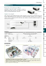
City Multi
*1
Indoor Unit
Maximum Meter
Via Branch Box
Only City Multi
*1
Indoor Unit
Only Branch Box
Connection
• The capacity and number of indoor units when using a branch box differs from situations when no branch box is
used. Refer to the installation manual for each outdoor unit for more information. Moreover, the indoor unit lineup
varies from country to country, so contact your local distributor for details.
• Capacity calculations for the entire system will depend on the connected indoor unit. Refer to the installation
manual for more information.
• Piping lengths also differ when using a branch box. Refer to the installation manual for each outdoor unit for more
information.
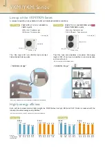
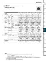
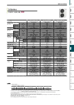
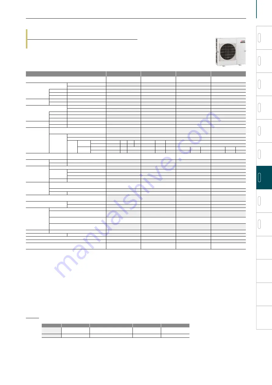
S-Series
PUMY-SP VKMD-A(-BS)
Model
PUMY-SP80VKMD-A(-BS) PUMY-SP112VKMD-A(-BS)
PUMY-SP125VKMD-A(-BS)
PUMY-SP140VKMD-A(-BS)
Power source
1-phase 220-230-240 V, 50 Hz;
1-phase 220 V, 60 Hz
1-phase 220-230-240 V, 50 Hz;
1-phase 220 V, 60 Hz
1-phase 220-230-240 V, 50 Hz;
1-phase 220 V, 60 Hz
1-phase 220-230-240 V, 50 Hz;
1-phase 220 V, 60 Hz
Cooling capacity
*1 kW
9.0
12.5
14.0
15.5
(Nominal)
*1 Btu/h
30,700
42,700
47,800
52,900
Power input kW
2.11
3.10
3.84
4.38
Current input A
9.79-9.36-8.97
14.38-13.75-13.18
17.81-17.04-16.33
20.32-19.43-18.62
COP
kW/kW
4.27
4.03
3.65
3.54
Temp. range of
cooling
Indoor
W.B.
15 to 24°C (59 to 75°F)
15 to 24°C (59 to 75°F)
15 to 24°C (59 to 75°F)
15 to 24°C (59 to 75°F)
Outdoor
D.B.
-5 to 52°C *3,*4 (23 to 126°F) -5 to 52°C *3,*4 (23 to 126°F) -5 to 52°C *3,*4 (23 to 126°F) -5 to 52°C *3,*4 (23 to 126°F)
Heating capacity
*2 kW
10.0
14.0
16.0
16.5
(Nominal)
*2 Btu/h
34,100
47,800
54,600
56,300
Power input kW
2.27
3.17
3.90
4.02
Current input A
10.53-10.07-9.65
14.70-14.06-13.48
18.09-17.30-16.58
18.65-17.83-17.09
COP
kW/kW
4.41
4.42
4.10
4.10
Temp. range of
heating
Indoor
D.B.
15 to 27°C (59 to 81°F)
15 to 27°C (59 to 81°F)
15 to 27°C (59 to 81°F)
15 to 27°C (59 to 81°F)
Outdoor
W.B.
-20 to 15°C (-4 to 59°F)
-20 to 15°C (-4 to 59°F)
-20 to 15°C (-4 to 59°F)
-20 to 15°C (-4 to 59°F)
Indoor unit
connectable
Total capacity
50 to 130% of
outdoor unit capacity
50 to 130% of
outdoor unit capacity
50 to 130% of
outdoor unit capacity
50 to 130% of
outdoor unit capacity
Model/
Quantity
CITY MULTI
P10-P100/9
P10-P140/12
P10-P140/12
P10-P140/12
Branch box
P22-P80/5
P22-P100/7
P22-P100/8
P22-P100/8
Mixed
system
Branch box
1 unit
CITY MULTI P10-P100
5
4
2 P10-P140
5
4
P10-P140/5
P10-P140/5
Branch box P22-P100
2
3
4 P22-P100
4
5
P22-P100/5
P22-P100/5
Branch box
2 units
CITY MULTI P10-P100
3
2
P10-P140
3
2
P10-P140
3
2
P10-P140
3
2
Branch box P22-P100
3
4
P22-P100
5
6
P22-P100
6
7
P22-P100
7
8
Sound pressure level
(measured in anechoic room)
dB <A>
51/54
52/54
53/56
54/56
Refrigerant piping
diameter
Liquid pipe
mm (inch)
9.52 (3/8) Flare
9.52 (3/8) Flare
9.52 (3/8) Flare
9.52 (3/8) Flare
Gas pipe
mm (inch)
15.88 (5/8) Flare
15.88 (5/8) Flare
15.88 (5/8) Flare
15.88 (5/8) Flare
Fan
Type × Quantity
Propeller Fan × 1
Propeller Fan × 1
Propeller Fan × 1
Propeller Fan × 1
Airflow rate
m³/min
75/75
77/75
81/83
81/83
L/s
1250/1250
1283/1250
1350/1383
1350/1383
cfm
2649/2649
2719/2649
2861/2931
2861/2931
Motor output kW
0.20 × 1
0.20 × 1
0.20 × 1
0.20 × 1
Compressor
Type × Quantity
Twin rotary hermetic
compressor × 1
Twin rotary hermetic
compressor × 1
Twin rotary hermetic
compressor × 1
Twin rotary hermetic
compressor × 1
Starting method
Inverter
Inverter
Inverter
Inverter
Motor output kW
2.1
3.1
3.5
3.7
External finish
Galvanized Steel Sheet
Munsell No. 3Y 7.8/1.1
Galvanized Steel Sheet
Munsell No. 3Y 7.8/1.1
Galvanized Steel Sheet
Munsell No. 3Y 7.8/1.1
Galvanized Steel Sheet
Munsell No. 3Y 7.8/1.1
External dimension H × W × D
mm
981 × 1,050 × 330 (+25)
981 × 1,050 × 330 (+25)
981 × 1,050 × 330 (+25)
981 × 1,050 × 330 (+25)
inch
38-5/8 × 41-3/8 × 13 (+1)
38-5/8 × 41-3/8 × 13 (+1)
38-5/8 × 41-3/8 × 13 (+1)
38-5/8 × 41-3/8 × 13 (+1)
Protection
devices
High pressure protection
High pressure Switch
High pressure Switch
High pressure Switch
High pressure Switch
Inverter circuit (COMP./FAN)
Overcurrent detection, Overheat
detection(Heat sink thermistor)
Overcurrent detection, Overheat
detection(Heat sink thermistor)
Overcurrent detection, Overheat
detection(Heat sink thermistor)
Overcurrent detection, Overheat
detection(Heat sink thermistor)
Compressor
Compressor thermistor,
Overcurrent detection
Compressor thermistor,
Overcurrent detection
Compressor thermistor,
Overcurrent detection
Compressor thermistor,
Overcurrent detection
Fan motor
Overheating, Voltage
protection
Overheating, Voltage
protection
Overheating, Voltage
protection
Overheating, Voltage
protection
Refrigerant
Type × original charge
R410A × 3.5 kg (8 lb)
R410A × 3.5 kg (8 lb)
R410A × 3.5 kg (8 lb)
R410A × 3.5 kg (8 lb)
Net weight
kg (lb)
93 (205)*5
93 (205)*5
93 (205)*5
93 (205)*5
Heat exchanger
Cross Fin and Copper tube Cross Fin and Copper tube Cross Fin and Copper tube Cross Fin and Copper tube
Defrosting method
Reversed refrigerant circuit Reversed refrigerant circuit Reversed refrigerant circuit Reversed refrigerant circuit
Optional parts
Joint: CMY-Y62-G-E
Header: CMY-Y64/68-G-E
Joint: CMY-Y62-G-E
Header: CMY-Y64/68-G-E
Joint: CMY-Y62-G-E
Header: CMY-Y64/68-G-E
Joint: CMY-Y62-G-E
Header: CMY-Y64/68-G-E
Notes:
*1,*2 Nominal conditions
*3 10 to 52°C(D.B.): When connecting following models such as PKFY-P10/15/20/25/32VLM, PFFY-P20/25/32VLE(R)M, PFFY-P20/25/32VKM, and M series, S series, and P series type indoor unit.
*4 −15 to 52°C(D.B.): When using an optional air protect guide [PAC-SH95AG-E]. However, this condition does not apply to the indoor unit listed in *3.
*5 94 (207), for PUMY-SP80/112/125/140VKMD-A-BS.
*Nominal conditions *1,*2 are subject to ISO 15042.
*Due to continuing improvement, above specifications may be subject to change without notice.
Indoor
Outdoor
Pipe length
Level diff erence
Cooling
27ºC DB/19ºC WB
(81ºF DB/66ºF WB)
35ºC DB(95ºF DB)
7.5m (24-9/16ft.)
0m (0ft.)
Heating
20ºC DB(68ºF DB)
7ºC DB/6ºC WB(45ºF DB/43ºF WB)
7.5m (24-9/16ft.)
0m (0ft.)
97
VRF
Y-Series
VRF
Lineup
VRF
R2-Series
VRF
Zubadan
VRF
WY-Series
VRF
WR2-Series
VRF
S-Series
VRF
Indoor Units
Ventilation
Systems
Technologies and Functions
Remote Controller
Hot Water Solution
VRF
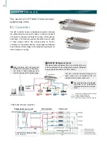
BC Controllers
VRF
S-Series
SPECIFICATIONS
Summary of Contents for City Multi R2 Series
Page 1: ...CM20AN E NZ VRF City Multi Product Catalogue ...
Page 101: ...BC Controllers 101 ...
Page 112: ...Indoor Units VRF 112 ...
Page 114: ...Ceiling Cassette Type 4 Way Airflow Type 114 ...
Page 122: ...Ceiling Cassette Type 2 Way Airflow Type 122 ...
Page 128: ...Ceiling Concealed Type 128 ...
Page 150: ...Wall Mounted Type 150 ...
Page 154: ...Floor Standing Type 154 ...
Page 181: ...Ventilation Systems 181 ...
Page 190: ...Remote Controllers 190 ...


