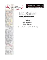
background image

COMPUTER PRODUCTS

COMPUTER PRODUCTS

COMPUTER PRODUCTS

COMPUTER PRODUCTS

COMPUTER PRODUCTS

CM33-TL

System Board

User Manual

(Manual Part Number MAN-0CM33-001)

Summary of Contents for CM33-TL

Page 1: ...COMPUTER PRODUCTS COMPUTER PRODUCTS COMPUTER PRODUCTS COMPUTER PRODUCTS COMPUTER PRODUCTS CM33 TL System Board User Manual Manual Part Number MAN 0CM33 001 ...

Page 2: ...products produced and or offered by other companies The product and company names may be trademarked and are the sole property of their respective owners MEAU and or AVG Automation disclaims any proprietary interest in the marks and names of others Manual P N MAN 0CM33 001 Designed and Manufactured specifically for Mitsubishi Electric Automation Inc by AVG Mitsubishi Electric Automation Inc MEAU 5...

Page 3: ...tors 11 PS 2 Mouse and PS 2 Keyboard Ports 11 Parallel Port 12 Universal Serial Bus Port 13 VGA Port 14 RJ45 Fast Ethernet Port CM33 TL 15 CHAPTER 3 AWARD BIOS SETUP UTILITY Basic Input Output System 17 Standard CMOS Features 17 Advanced BIOS Features 20 Advanced Chipset Features 24 Integrated Peripherals 26 Power Management Setup 29 PnP PCI Configuration 32 PC Health Status 34 Frequency Voltage C...

Page 4: ... Products MAN 0CM33 001 CONTENTS APPENDIX B TROUBLESHOOTING Troubleshooting Checklist B 1 Monitor Display B 1 Power Supply B 2 Floppy Drive B 2 Hard Drive B 2 Parallel Port B 2 Serial Port B 3 Keyboard B 3 System Board B 3 ...

Page 5: ... their functions You will be shown how to install a DIM Module and set Jumpers to configure the CPU to meet your own needs Award BIOS Setup Utility This chapter describes how to set up the BIOS configurations Supported Software This chapter discusses the software utilities drivers that was provided with your computer Chapters Appendix A System Error Messages This appendix provides you with System ...

Page 6: ... these performance demands the CM33 TL Embedded Sys tem Board has been installed in your MC400 Series Industrial Node Computer The CM33 TL is a Micro ATX Style CPU Card for a Single Intel Pentium III Processor in a 370 pin socket This manual provides you with the information you need to configure the CM33 TL and get your MC400 Series Computer up and running in accordance with your application requ...

Page 7: ...M 3 3V PC 133 SDRAM DIMM for 133 MHz FSB processors Note If you are using more than one DIMM ensure that you insert the same type of DIMMs into the DIMM sockets Using different types VCM or PC SDRAM of DIMMs may cause problems Expansion Slots The system board is equipped with 3 dedicated PCI slots Onboard Graphics Features Integrated rCADE3D 2D 3D Video accelerator Shares 8MB of the system memory ...

Page 8: ...s wire for management ATX Double Deck Ports PC 99 color coded connectors Two USB ports One RJ45 LAN port One NS16C550A compatible DB 9 serial port One DB 15 VGA port One DB 25 Parallel port One mini DIN 6 PS 2 mouse port One mini DIN 6 PS 2 keyboard port Connectors Two IDE connectors One floppy drive interface supports up to two 2 88MB floppy drives One ATX power supply One Wake On LAN connector O...

Page 9: ...ation and stores this information in the DMI pool which is a part of the system board s Plug and Play BIOS DMI along with the appropriately net worked software is designed to make inventory maintenance and trouble shooting of computer systems easier Refer to Chapter 4 for instructions on using the DMI utility System Health Monitor Functions The system board is capable of monitoring the following s...

Page 10: ... power returns after an AC power failure you may choose to either power on the system manually let the system power on automatically or return to the state where you left off before power failure occurred Refer to PWR Lost Resume State in the Power Management Setup section in Chapter 3 for more information Virus Protection Most viruses today destroy data stored in hard drives The system board is d...

Page 11: ...7 MAN 0CM33 001 MC Series Computer Products 2 HARDWARE INSTALLATION Hardware Installation CM33 TL System Board Layout ...

Page 12: ...SDRAM DIMM PC SDRAM Syn chronous Dynamic Random Access Memory uses a fast memory interface technology that includes using the clock on the chip to synchronize with the CPU clock so that the timing of the memory chips and the timing of the CPU are synchronized This saves time during transmission of data subsequently increasing system performance Refer to Chapter 1 System Memory section for detailed...

Page 13: ...ON Wait for a few seconds and set JP3 back to its default setting pins 1 and 2 ON 3 Plug the power cord and power on the system If your reasons for clearing the CMOS data is due to incorrect setting of the processor s bus clock in the BIOS proceed to step 4 4 After powering on the system press Del to enter the main menu of the BIOS 5 Select the Frequency Voltage Control submenu and press Enter 6 S...

Page 14: ...Products MAN 0CM33 001 2 HARDWARE INSTALLATION Jumper Settings for Selecting the USB Power Power Select for USB 1 and 2 JP1 and This jumper is used to select the power for the USB devices that are con nected to the USB ports ...

Page 15: ...d Purple ports both at location J1 of the ATX double deck ports of the system board The PS 2 mouse port uses IRQ12 If a mouse is not con nected to this port the system will reserve IRQ12 for other expansion cards Caution Make sure to turn off your computer prior to connecting or dis connecting a mouse or keyboard Failure to do so may damage the sys tem board PORTS AND CONNECTORS ...

Page 16: ...rinter It supports Normal ECP and EPP modes You can set the port s mode in the Integrated Peripherals submenu of the BIOS Setting Function Normal Allows normal speed operation but in one direction only ECP Extended Capabilities Port Allows parallel port to operate in bidirectional mode and at a speed faster than the SPP s data transfer rate EPP Enhanced Allows bidirectional parallel port operation...

Page 17: ...ata exchange between your computer and a wide range of simultaneously accessible external Plug and Play peripherals You must have the proper drivers installed in your oper ating system to use the USB ports Refer to your operating system s manual or documentation Two onboard USB ports J8 Black are located at the ATX double deck ports of the board ...

Page 18: ...y be used with an analog video monitor Connect the monitor s 15 pin D shell cable connector to the VGA port J3 Blue lo cated at the ATX double deck ports of the board Some monitors have a switch that chooses between analog and TTL or digital operation If your monitor has such a switch set it for analog ...

Page 19: ...ARE INSTALLATION RJ45 Fast Ethernet Port CM33 TL The system board is equipped with an onboard RJ45 fast ethernet LAN port at location J8 of the ATX double deck ports It allows the system board to con nect to a local area network by means of a network hub ...

Page 20: ...16 MC Series Computer Products MAN 0CM33 001 2 HARDWARE INSTALLATION This page intentionally left blank ...

Page 21: ... Utility for the Award BIOS After you power up the system the BIOS message appears on the screen and the memory count begins After the memory test the following message will appear on the screen Press DEL to enter setup If the message disappears before you respond restart the system or press the Reset button You may also restart the system by pressing the Ctrl Alt and Del keys simultaneously When ...

Page 22: ...om 00 to 59 IDE Primary Master IDE Primary Slave IDE Secondary Master and IDE Secondary Slave Move the cursor to IDE Primary Master IDE Primary Slave IDE Second ary Master or IDE Secondary Slave field then press Enter IDE HDD Auto Detection Detects the parameters of the drive The parameters will automati cally be shown on the screen IDE Primary Secondary Master Slave If you wish to define your own...

Page 23: ...acity Video This field selects the type of video adapter used for the primary system moni tor Although secondary monitors are supported you do not have to select the type The default setting is EGA VGA EGA VGA Enhanced Graphics Adapter Video Graphics Array For EGA VGA SVGA and PGA monitor adapters CGA 40 Color Graphics Adapter Power up in 40 column mode CGA 80 Color Graphics Adapter Power up in 80...

Page 24: ... Advanced BIOS Features The Advanced BIOS Features allows you to configure your system for basic operation Some entries are defaults required by the system board while oth ers if enabled will improve the performance of your system or let you set some features according to your preference The screen above lists all the fields available in the Advanced BIOS Features submenu for you to reference In t...

Page 25: ...ory access The default value is enabled CPU L2 Cache ECC Checking The processors supported by the system board come with built in Level 2 cache By default ECC is enabled to check the Level 2 cache If you are not using this function set this field to Disabled Processor Serial Number This field will appear only when you are using Intel s Pentium III or later pro cessor These processors come with an ...

Page 26: ...rein the function of the nu meric keypad is the number keys When set to Off the function of the numeric keypad is the arrow keys Typematic Rate Setting Disabled Continually holding down a key on your keyboard will cause the BIOS to report that the key is down Enabled The BIOS will not only report that the key is down but will first wait for a moment and if the key is still down it will begin to re...

Page 27: ...ives The drive will provide sufficient notice to the system or user to back up data prior to the drive s failure The default is Disabled If you are using hard drives that support SMART set this field to Enabled SMART is supported in ATA 33 or later hard drives Small Logo EPA Show Enabled The EPA logo will appear during system boot up Disabled The EPA logo will not appear during system boot up Onbo...

Page 28: ...s would be if you discovered some incompatibility or that data was being lost while using your system DRAM Timing by SPD Enabled The EEPROM on a PC SDRAM DIMM that has SPD Serial Presence Detect data structure stores information about the module such as the memory type memory size memory speed etc When this field is enabled the system will run according to the information in the EEPROM Disabled It...

Page 29: ... to the system However if your I O devices are capable of fast I O select Disabled to speed up system operation Frame Buffer Size The options are 2M 4M and 8M OnChip USB This field is used to enable or disable the onboard USB controller supported by the chipset If you are using a USB peripheral make sure to set this field to Enabled USB Keyboard Support This field will appear only if the OnChip US...

Page 30: ...d if you want to add a differ ent hard drive controller IDE Prefetch Mode This allows data and addresses to be stored in the internal buffer of the chip thus reducing access time Enable this field to achieve better performance IDE Primary Master Slave PIO and IDE Secondary Master Slave PIO PIO means Programmed Input Output Rather than have the BIOS issue a series of commands to effect a transfer t...

Page 31: ... select whether to initialize AGP or PCI first when the sys tem boots AGP When the system boots it will first initialize AGP PCI Slot When the system boots it will first initialize PCI IDE HDD Bock Mode Enabled The IDE HDD uses the block mode The system BIOS will check the hard disk drive for the maximum block size the system can transfer The block size will depend on the type of hard disk drive D...

Page 32: ...nd will depend on the type and speed of your device Refer to your peripheral s manual for the best option Normal Allows normal speed operation but in one direction only ECP Extended Capabilities Port Allows parallel port to operate in bidirectional mode and at a speed faster than the normal mode s data transfer rate EPP Enhanced Parallel Port Allows bidirectional parallel port operation at maximum...

Page 33: ...tion make sure this field is enabled then select S3 STR in the ACPI Suspend Type field Power Management Move the cursor to this field and press Enter The Power Management HDD Power Down Doze Mode and Suspend Mode fields will appear Power Management This field allows you to select the type or degree of power saving by changing the length of idle time that elapses before the Doze Mode and Suspend Mo...

Page 34: ...CPU and onboard peripherals will be shut off ACPI Suspend Type This field is used to select the type of Suspend mode S1 POS Enables the Power On Suspend function S3 STR Enables the Suspend to RAM function Refer to using the Suspend to RAM Function in appendix A for more information PM Control by APM Yes An Advanced Power Management device will be activated to enhance the Max Power Saving mode and ...

Page 35: ...elease again in less than 4 sec to restore Pushing the power button for more than 4 seconds will power off the system Instant Off Pressing then releasing the power button at once will immediately power off your system PWR Lost Resume State Keep Off When power returns after an AC power failure the system s power is off You must press the Power button to power on the system Turn On When power return...

Page 36: ...ions This section describes configuring the PCI bus system It covers some very technical items and it is strongly recommended that only experienced users make any changes to the default settings Reset Configuration Data Enabled The BIOS will reset the Extended System Configuration Data ESCD once automatically It will then recreate a new set of configuration data Disabled The BIOS will not reset th...

Page 37: ...A or not The default value is Disabled Enabled MPEG ISA VESA VGA cards work with PCI VGA Disabled MPEG ISA VESA VGA cards do not work with PCI VGA Assign IRQ for VGA When Enabled the system automatically assigns an IRQ for the VGA card installed Your VGA card will need an IRQ only when using the video capture function of the card If you are not using this function and a new device re quires an IRQ...

Page 38: ...Revolutions per Minute Vcore This field shows the voltage of the processor 3 3V 5V and 12V These fields show the output voltage of the power supply Note The onboard hardware monitor function is capable of detecting system health conditions but if you want a warning message to pop up or a warning alarm to sound when an abnormal condition occurs you must install the VIA Hardware Monitor utility This...

Page 39: ...instructing you to press Del in order to enter the man menu of the BIOS If you did not press Del the system will automatically power off after the 5 warning beeps You may either 1 Press Del then enter a new CPU temperature limit or 2 Allow the system to power off after the 5 warning beeps then check whether the heatsink and fan are mounted properly onto the CPU because high CPU temperature may be ...

Page 40: ... by an engineer or technician Clock by Slight Adjust Do not change this field Load Fail Safe Defaults This option loads the troubleshooting default values permanently stored in the ROM chips These settings are not optimal and turn off all high performance features You should use these values only if you have hardware problems Highlight this option in the main menu and press Enter The message below...

Page 41: ...he password You are limited to eight characters ALWAYS KEEP A RECORD OF PASSWORDS IN A SAFE PLACE When done the following message will appear Confirm Password You are asked to verify the password Type in exactly the same password If you type in a wrong password you will be prompted to enter the correct pass word again To delete or disable the password function highlight Set Super visor Password an...

Page 42: ...The message below will appear Quit Without Saving Y N N Type Y and press Enter The system will reboot and you will once again see the initial diagnostics on the screen If you wish to make any changes to the setup press Ctrl Alt Esc simultaneously or Del after memory testing is done Updating the BIOS To update the BIOS you will need the new BIOS file and a flash utility AWDFLASH EXE You can downloa...

Page 43: ...recommend that you use the Default Setting which is the ideal setting that would keep the system in good working condition Note Use this utility on in Windows 95 98 98SE ME 2000 XP or NT 4 0 operating systems To install the utility insert the CD into a remote disk drive Download the VIA Hardware Monitor Utility Onboard LAN Drivers for Windows The onboard LAN drivers included on the CD do not suppo...

Page 44: ...40 MC Series Computer Products MAN 0CM33 001 This page intentionally left blank 4 SUPPORTED SOFTWARE ...

Page 45: ..._______________________________________________________ ______________________________________________________________________________________________ __________________________________________________________________________________________ __________________________________________________________________________________________ ___________________________________________________________________...

Page 46: ..._____________________________ ____________________________________________________________________________________________ _____________________________________________________________________________________ ___________________________________________________________________________________ _________________________________________________________________________________________ _________________...

Page 47: ...f the BIOS detects an error during the POST This list indicates the error messages for all Awards BIOSes CMOS BATTERY HAS FAILED The CMOS battery is no longer functional It should be replaced Caution Danger of explosion if battery is incorrectly replaces Replace only with the same or equivalent type recommended by the manufac turer Dispose of used batteries according to the battery manufacturer s ...

Page 48: ...cts that the keyboard is locked Keyboard controller is pulled low Keyboard error or no keyboard present Cannot initialize the keyboard Make sure the keyboard is attached correctly and no keys are being pressed during boot Manufacturing POST loop System will repeat POST procedure infinitely while the keyboard controller is pull low This is also used for the M B burn in test at the factory BIOS ROM ...

Page 49: ...trols are adjusted properly 6 All add in boards in the expansion slots are seated securely 7 Any add in board you have installed is designed for your system and is set up correctly Monitor Display If the display screen remains dark after the system is turned on 1 Make sure that the monitor s power switch is on 2 Check that one end of the monitor s power cord is properly attached to the monitor and...

Page 50: ...The floppy diskette may not be formatted Format the diskette and try again 2 The diskette may be write protected Use a diskette that is not write protected 3 You may be writing to the wrong drive Check the path statement to make sure you are writing to the targeted drive 4 There is not enough space left on the diskette Use another diskette with adequate storage space Hard Drive Hard disk failure M...

Page 51: ... the cable or the serial device has a problem If the serial device works the problem may be due to the onbaord I O or the address setting 4 Make sure the COM settings and I O address are configured correctly Keyboard Nothing happens when a key on the keyboard was pressed 1 Make sure the keyboard is properly connected 2 Make sure there are no objects resting on the keyboard and that no keys are pre...

Page 52: ...B 4 MC Series Computers MAN 0CM33 001 APPENDIX B TROUBLESHOOTING This page intentionally left blank ...

Reviews: