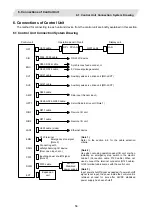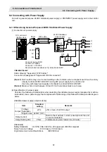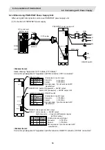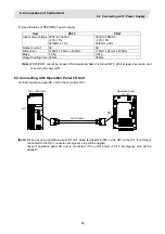
background image

6. Connections of Control Unit 

6.8 Connecting with Expansion Unit 


66 

6.8.3 Connecting I/O Devices via CC-Link


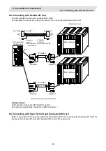
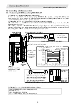
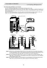
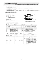
CC-Link unit works as master station or local station of CC-Link (Ver.2 mode). 
Expansion unit (FCU7-EX891) and CC-Link unit (FCU7-HN576) are required to connect I/O devices via 
CC-Link. Mount the expansion unit on the right side of the control unit, and install the CC-Link unit in the slot 
of the expansion unit. 
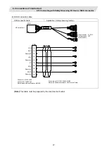
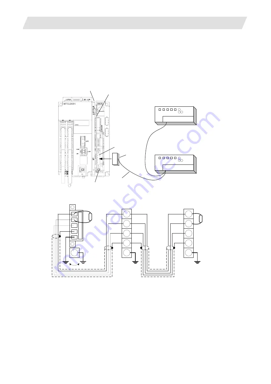
CC-Link uses the dedicated cable. Connect the cable to the terminal block provided with the CC-Link unit. 
Make sure to attach the terminator, provided with the CC-Link unit, to the final station unit.


Expansion unit
(FCU7-EX891)

CC-Link unit(FCU7-HN576)

CC-Link network

connector

FG terminal

block

CC-Link

remote I/O station

CC-Link

remote I/O station

CC-Link cable

Terminal

block


DA


DB


DG


SLD


FG

DA

FG

SLD

DG

DB

DA

FG

SLD

DG

DB

FG

Terminator

(Note 2)

Terminator

(Note 2)

Use either
for wiring

(Note 3)

NC side CC-Link
unit terminal block

Remote I/O station

terminal block

Remote I/O station

terminal block

Shielded twisted cable (with 3 wires) 

(Note 1)

Shielded twisted cable (with 3 wires) 

(Note 1)

FG

FG

FG

FG


(Note 1)

 Unless the CC-Link dedicated cable is used, CC-Link system does not guarantee its operation. 

For the specifications of the CC-Link dedicated cable and the inquiries, see the homepage of the 
CC-Link Partner Association (http://www.cc-link.org/). (Click “Product Information”.)


(Note 2)

 Use the terminator provided with the CC-Link unit. The value of the terminator depends on the 

cable used: 110

Ω

 when the CC-Link dedicated cable is used, 130

Ω

 when the CC-Link dedicated 

high performance cable is used.


(Note 3)

 Use either the FG terminal on the NC side CC-Link terminal block or the FG terminal block just 

below the CC-Link terminal block to connect to the ground of the electric cabinet.


Summary of Contents for CNC 700 Series

Page 1: ......

Page 2: ... trademarks or trademarks of Intel Corporation and its subsidiaries in the United States and other countries SanDisk and SanDisk logos are registered trademarks of SanDisk Corporation U S A MELDAS is a registered trademark of Mitsubishi Electric Corporation Other company and product names that appear in this manual are registered trademarks or trademarks of their respective companies ...

Page 3: ...ine tool builder before use Refer to the Instruction Manual issued by each machine tool builder for details on each machine tool Some screens and functions may differ depending on each NC system or version and some functions may not be possible Please confirm the specifications before use The numerical control unit is configured of the control unit display unit operation board servo drive unit spi...

Page 4: ...ION DANGER When the user could be subject to imminent fatalities or serious injuries if handling is mistaken WARNING When the user could be subject to fatalities or serious injuries if handling is mistaken CAUTION When the user could be subject to minor or moderate injuries or the property could be damaged if handling is mistaken Note that the items under CAUTION could lead to serious consequences...

Page 5: ...ore wiring works inspections or connecting with peripheral devices Failure to observe this could result in electric shocks Earth ground the controller drive unit and motor according to the local laws In Japan ground the 200V Series input products with Class C or higher protective grounding and the 400V Series input with Class D or higher protective grounding All wiring works maintenance and inspec...

Page 6: ...vomotor be careful so that your hand or property will not be trapped in the motors or other metal objects Also keep the devices with low magnetic tolerance away from the product CAUTION Do not apply voltages to the connectors or terminals other than voltages indicated in the connection manual for the controller or specifications manual for the drive unit Failure to observe this could cause the dev...

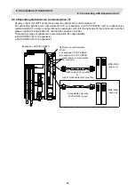
Page 7: ... to contact or enter the motor Prevent the cutting chips from being accumulated on the motor as they easily soak up oil When installing the motor facing upwards take measures on the machine side so that gear oil etc will not enter the motor shaft Do not remove the detector from the motor The detector installation screw is treated with sealing Do not allow foreign matters especially conductive fore...

Page 8: ...olerable radial load of the shaft Do not use a rigid coupling as an excessive bending load will be applied on the shaft and could cause the shaft to break Do not apply a load exceeding the tolerable level onto the motor shaft The shaft or bearing could be damaged Before using this product after a long period of storage please contact the Mitsubishi Service Station or Service Center Following the U...

Page 9: ...ect the connection cables between each unit while the power is ON Do not connect or disconnect the PCBs while the power is ON Do not pull the cables when connecting disconnecting it Securely tighten the cable connector fixing screw or fixing mechanism Insufficient fixing could result in deviation during operation Always treat the shield cables indicated in the Connection Manual with grounding meas...

Page 10: ...or and each regenerative resistor with the designated combination Failure to observe this could result in fires or faults The combination of the motor and drive unit that can be used is determined Be sure to check the models of motor and drive unit before test operation The brakes electromagnetic brakes mounted in the servomotor are used for the purpose of holding and must not be used for normal b...

Page 11: ...rcuit structure for the electromagnetic brake s operation circuit so that the brakes will activate even when the external emergency stop signal is issued Motor Electro magnetic brake Shut off with motor brake control output Shut off with CNC brake control PLC output MBR EMG 24VDC The machine could suddenly restart when the power is restored after an instantaneous power failure so stay away from th...

Page 12: ...ot short circuit charge overheat incinerate or disassemble the battery The hard disk unit has a service life and must be replaced before its expiration As a precautionary measure always back up the customer s data stored in the hard disk unit The safety of the customer s data stored in the hard disk unit cannot be guaranteed There may be a unit filled with substitute Freon in the heat radiating fi...

Page 13: ...ansion Unit FCU7 EX891 10 2 3 13 Expansion Card 10 2 3 14 External Power Supply Unit PD25 PD27 10 3 General Specifications Environment Conditions 11 3 1 Environment Conditions in Operation Box 11 3 2 Environment Specifications in Electric Cabinet 12 3 3 Remote I O Unit 13 3 4 Servo Spindle 13 3 5 Heat Radiation Countermeasures 14 3 6 Noise Countermeasures 17 3 6 1 Connection of FG Frame Ground 17 ...

Page 14: ... DX121 FCUA DX141 51 5 8 Manual Pulse Generator 52 5 8 1 UFO 01 2Z9 52 5 8 2 HD60 53 5 9 Synchronous Feed Encoder 54 5 9 1 OSE 1024 3 15 68 54 5 10 F Installation Plate 55 6 Connections of Control Unit 56 6 1 Control Unit Connection System Drawing 56 6 2 Connecting with Power Supply 57 6 2 1 When Using General Purpose 24VDC Stabilized Power Supply 57 6 2 2 When Using PD25 PD27 Power Supply Unit 58...

Page 15: ... Station No When Using Multiple Remote I O Units 97 8 2 4 Outline of Digital Signal Input Circuit 99 8 2 5 Outline of Digital Signal Output Circuit 101 8 2 6 Outline of Analog Signal Output Circuit 102 8 2 7 Outline of Analog Signal Input Circuit 103 8 2 8 Connection of FCUA DX10 14 Unit and Machine Control Signal 104 8 2 9 Connection of FCUA DX14 Unit and Analog Input Output Signal 106 8 2 10 Con...

Page 16: ...l Body 157 1 4 2 Measures for Door 158 1 4 3 Measures for Power Supply 158 1 5 Measures for Wiring in Panel 159 1 5 1 Precautions for Wiring in Panel 159 1 5 2 Shield Treatment of Cables 160 1 6 EMC Countermeasure Parts 161 1 6 1 Shield Clamp Fitting 161 1 6 2 Ferrite Core 161 1 6 3 Surge Absorber 163 1 6 4 Selection of Stabilized Power Supply 165 Appendix 2 Cable 166 2 1 G014 Cable 168 2 2 G015 C...

Page 17: ... Operation Panel I O Unit 196 3 2 1 Manual Pulse Generator Connecting Connector MPG 196 3 2 2 24VDC Input Connector DCIN 196 3 2 3 Remote I O Unit Connecting Connector RIO3 196 3 2 4 Machine Input Output Connector CG31 CG32 CG33 CG34 197 3 2 5 Reset Switch Input Connector NCRST 198 3 2 6 Emergency Stop Input Connector EMGIN 198 3 2 7 Ethernet Connector LAN 199 3 2 8 24VDC Input Connector DCIN 199 ...

Page 18: ...ector 242 5 3 5 Drive Unit Side Main Circuit Connector 243 5 3 6 Spindle Detector Connector 245 Appendix 6 Precautions for Wiring M700 Series 247 6 1 Connecting the Optical Fiber Cable 247 6 1 1 Outline of Optical Fiber Cable and Names of Each Part 247 6 1 2 Precautions for Handling Optical Fiber Cable 247 6 1 3 Precautions for Laying Optical Fiber Cable 248 6 2 Precautions for Connecting Peripher...

Page 19: ...Appendix 8 Precautions for Use of Peripheral Devices and Commercially Available Devices 267 Appendix 9 Precautions for Use of Peripheral Devices and Commercially Available Devices 268 ...

Page 20: ...ghly and understand the product s functions and performance before starting to use This manual is written on the assumption that all option functions are added but the actually delivered device may not have all functions The unit names cable names and various specifications are subject to change without notice Please confirm these before placing an order ...

Page 21: ...R R ID E M O D E S E LE C T H A N D L E S T E P M U L T IP L IC A T IO N 100000 1 10 100 1000 5000 10000 50000 TAP E STE P R AP ID JO G MEM M D I R P O IN T R E T U R N Y X 4 Z HANDLE R A P ID T R A V E R S E O V E R R ID E 1 25 50 100 180 40 60 80 100 120 140 160 90 70 50 30 20 10 0 110 130 150 170 190 200 7200 20 52 200 520 1000 2000 3700 270 100 27 10 2 1 0m m m in 720 1400 2700 5200 10000 1400...

Page 22: ...USB2 FRONT_OUT PC Keyboard F120 Cable IC memory card interface USB3 interface OPI RIO2 MDS D DH LAN LAN Max 256 256 Max 256 256 DX101 24Vdc RIO1 DCIN RIO2 Remote I O unit Machine I O To next unit or terminator Max 128 128 24Vdc F070 Cable DCIN Sync Encoder FCUA R050 R054 Cable ENC SIO Max 64 64 G013Cable max 20m Keyboard Unit FCU7 KB021 KB022 KB041 G290 Cable G291 Cable G301 Manual pulse generator...

Page 23: ...FDD CF USB1 SIO FRONT_OUT PC Keyboard ON OFF G170 Cable ON OFF F120 Cable HDD CF25 IC memory card interface USB interface OPI RIO2 MDS D DH LAN LAN Max 256 256 Max 256 256 DX101 24Vdc RIO1 DCIN RIO2 Remote I O unit Machine I O To next unit or terminator Max 128 128 24Vdc F070 Cable DCIN SIO G013 Cable max 20m Keyboard Unit FCU7 KB021 KB022 KB041 G290 Cable G291 Cable SKIP SH21 Cable SH21 Cable FCU...

Page 24: ...HN116 Display setting card HN091 M720 system compatible unit 24V input power supply card HN081 Memory card HN482 G123 cable Case set Export Trade Control Ordinance and Foreign Trade Ordinance noncompliant unit FCU7 MU011 M700 control unit set Main control card HN115 CPU card HN123 Display setting card HN091 M730 system compatible unit 24V input power supply card HN081 Memory card HN484 G123 cable ...

Page 25: ... Mount on front panel Use PD25 PD27 for power supply FCU7 DA445 xx 10 4 type color LCD display unit Wide view angle High performance version WindowsXPe compatible separated type 10 4 type VGA LCD Escutcheon Control card MIP12M2 G093 cable G291 cable F480 cable with front IC card FCU7 EP102 Pentium III 1 26GHz Control card 24VDC input Mounting method Mount on front panel Use PD25 PD27 for power sup...

Page 26: ...U7 DX771 Sink source input source output HN392 HN397 Mounting bracket G301 cable G310 cable Terminator R TM DI DO 64 points 64 points output 60mA Output insulation type Note 1 Display main body relay I F Manual pulse generator 3ch Emergency stop input Remote I O 1ch 128 points 128 points Note 1 All points of the DO are insulated with a photo coupler Thus 24V must be input from an external source f...

Page 27: ...DX111 Sink source input source output RX312 RX322 1 DI DO 64 points 48 points FCUA DX121 Sink source input source output analog output RX312 RX322 DI DO 64 points 48 points analog output 1 point FCUA DX141 Sink source input source output analog input output RX312 RX341 DI DO 32 points 32 points analog input 4 points analog output 1 point 2 3 6 Scan I O HR357 HR347 Type Function Configuration eleme...

Page 28: ...5VDC max 100mA 2 3 10 Hard Disk Unit FCU7 HD001 1 Type Function Configuration element Details FCU7 HD001 1 External memory device Hard disk Mounting plate cushioning rubber F140 cable 50cm Display unit Connect with FCU7 DA315 DA415 DA445 Installation method Mount on the back of FCU7 KB041 Note 1 Note 1 When not mounting the hard disk unit onto the back of the FCU7 KB041 face the cable lead out sid...

Page 29: ...ils FCU7 HN551 Optical servo communication I F 1ch HN551 FCU7 HN552 Optical servo communication I F 2ch HN552 FCU7 HN571 PROFIBUS DP 1ch HN571 FCU7 HN576 CC Link 1ch HN576 Expansion unit Connect with FCU7 EX891 Installation method Insert in expansion unit and fix with front cover 2 3 14 External Power Supply Unit PD25 PD27 Type Function Configuration element Details PD25 External power supply with...

Page 30: ...voltage 24VDC 5 ripple noise 240mV P P Power capacity max 2A max 2 5A max 3A max 2 8A max 3 3A max 0 5A Note 3 2 9A Max Note 4 0 7A Note 3 5 0A max Note 4 Required power specifi cations Instantaneous stop tolerance time AC 20ms or less when using external power supply unit PD25 PD27 24VDC 2ms or less Heating value 25W max 15W Typ 46W max 37W Typ 60W max 48W Typ 53 5W max 43W Typ 67 5W max 54W Typ ...

Page 31: ...operation 4 9m s2 0 5G or less Shock resistance During storage 29 4m s2 3 0G or less General specifi cations Working atmosphere No corrosive gases dust or oil mist Input power voltage 24VDC 5 Ripple noise 240mV P P 200V to 230VAC 10 15 50 60Hz 1Hz 200V to 480VAC 10 15 50 60Hz 3Hz Power capacity max 3A max control unit 1 3A expansion unit 1 7A Input current max 1 0A 200VAC at rated load 1 5A 240VAC...

Page 32: ...e 24VDC 5 Ripple noise 200mV P P Power capacity 24V 0 7A Note 2 24V 1 5A Note 2 24V 0 7A Note 2 Required Power specifi cation Instantaneous stop tolerance time Heating value Max 25W Note 3 30W Note 3 30W Note 3 Others Mass 0 5kg 0 6kg 0 6kg 0 6kg Note 1 The period is within one month Note 2 Amount consumed by control circuit Note 3 Differs according to the number of machine input operation points ...

Page 33: ...panel Caution 8 W m2 C can be applied only when the operation panel is so small that the internal temperature stays uniform 3 Points of caution for heat radiation countermeasures when designing mounting state Consider convection in operation panel eliminate heat spots Collect hot air at suction port of heat exchanger in operation panel 4 Criterion for internal temperature rise distribution data ΔT...

Page 34: ...as required 200 260 140 Display unit Agitating fan 600 120 500 Calculation example of heating value in operation panel 1 Calculation of unit heating value Heating value W Total heating value of units W 27W display unit operation panel I O unit Total heating value W by machine input D1 5 6W 24V total heating value when the 32 points are simultaneously turned ON 7 3mA 32 24V current consumption per ...

Page 35: ...stribution should also be excluded for the heat radiation area in principle Heat radiation area A 0 71mm2 0 6 0 12 0 6 0 5 2 0 26 0 14 0 2 0 12 0 5 2 Top surface Front rear surface Unit surface Both sides surface Operation panel cooling capacity W1 Calculate the cooling capacity to keep the temperature rise in the operation panel less than 10 C Cooling capacity W1 42 6W 6 A ΔT 3 Comparison of heat...

Page 36: ...3 6 1 Connection of FG Frame Ground The frame should basically be grounded at one ground point Connect the control unit s 0V RG to the FG on the 24V stabilized power supply Stabilized power supply AC input Main grounding plate for electric cabinet FG cable Control unit MITSUBISHI 24VDC 0V RG FG Short bar ...

Page 37: ... connected to the ground by using clamp fittings to stabilize the operation while preventing malfunctioning due to noise Refer to Appendix 1 6 1 3 6 3 Connecting Spark Killers Connect a spark killer on the coil or the contact in parallel for noise countermeasures Use spark killers which are 0 33 to 0 1 µF 10 to 120 Ω Coil Contact E Spark killer Spark killer ...

Page 38: ...trol Unit 19 4 Outline Drawing 4 1 Control Unit 1 Control unit only 12 11 13 15 3 4 5 1 2 6 7 8 9 10 14 Control unit Space required for wiring Space required for wiring Space required for connecting cables Space required at top ...

Page 39: ...g 4 1 Control Unit 20 2 With expansion unit 12 11 13 15 4 5 3 1 2 7 8 9 10 14 6 Control unit Expansion unit Space required at top Space required for wiring Space required for wiring Space required for connecting cables ...

Page 40: ...communication I F 11 RIO1 Remote IO unit I F 4 LAN1 NC LAN communication I F 12 RIO2 Remote IO unit I F 5 FG Frame ground 13 DCIN 24VDC input 6 SKIP Skip input 8ch 14 CF01 Power OFF input 7 OPI Operation panel I O unit I F Note 1 15 EMG External emergency stop input Note 2 8 SIO RS 232C communication I F 2ch Note 1 When not using OPI connector connect the terminator connector E TM optional Note 2 ...

Page 41: ...d into the unit FCU7 HN551 FCU7 HN552 Optical servo communication I F No Connector name Function 1 OPT2 Optical servo communication I F 1 2 2 OPT3 Optical servo communication I F Note OPT3 is mounted on FCU7 HN552 only FCU7 HN571 PROFIBUS DP 1ch No Connector name Function 1 CONF PROFIBUS DP configuration I F 2 NET PROFIBUS DP communication I F 1 2 3 3 FG Frame ground ...

Page 42: ...4 Outline Drawing 4 1 Control Unit 23 FCU7 HN576 CC Link 1ch No Connector name Function 1 CC LINK CC Link communication I F 1 2 2 FG Frame ground ...

Page 43: ...4 Outline Drawing 4 2 Display Unit 24 4 2 Display Unit 4 2 1 FCU7 DA201 8 4 type Space required for wiring Note The space of 40mm or more should be provided above the display unit for maintenance ...

Page 44: ...e 1 10 4 type WindowsCE compatible Space required for wiring Note The space of 30mm or more should be provided above the display unit for maintenance 2 10 4 type WindowsXP compatible Space required for wiring Note The space of 30mm or more should be provided above the display unit for maintenance ...

Page 45: ...play Space required for wiring Note The space of 30mm or more should be provided above the display unit for maintenance 4 10 4 type WindowsXP compatible with touch panel display Space required for wiring Note The space of 30mm or more should be provided above the display unit for maintenance ...

Page 46: ...4 Outline Drawing 4 2 Display Unit 27 4 2 3 FCU7 DA335 FCU7 DA435 15 type 1 15 type 400 320 20 110 Space required for wiring ...

Page 47: ... Outline Drawing 4 2 Display Unit 28 2 15 type with touch panel with menu key 400 320 20 110 Space required for wiring 3 15 type with touch panel without menu key 400 320 20 110 Space required for wiring ...

Page 48: ...ction specifications 2 FRONT_OUT Front IC card I F 3 INV LCD inverter power output 4 DCIN 24VDC input 5 MENUKEY Menu key connector 6 BAT Battery connector 7 SIO RS 232C communication I F 2ch No Connector name Function 8 PCLAN Personal computer LAN I F 9 LCD LCD I F 10 USB1 USB Ver1 1 I F 5V max 500mA 11 USB2 USB Ver1 1 I F 5V max 500mA 12 BATTERY Battery holder Battery Q6BAT 13 FAN2 External fan I...

Page 49: ...upply I F 24VDC input 5 MENUKEY Menu key connector 6 BAT Battery connector 7 SIO RS 232C communication I F 1ch 2ch 8 PCLAN Personal computer LAN I F 9 LCD LCD I F 10 USB1 USB Ver1 1 I F 5V max 500mA 11 USB2 USB Ver1 1 I F 5V max 500mA No Connector name Function 12 BATTERY Battery holder Battery Q6BAT 13 CF01 PD25 PD27 power supply I F ACFAIL input 14 CF24 PD25 PD27 power supply I F ON OFF input ou...

Page 50: ...P102 Front IC Card I F Unit 1 2 Explanation of front IC card I F unit and connector functions No Connector name Function 1 Memory card I F PC Card Standard ATA compliant memory card TYPEI TYPEII only 5VDC max 220mA 2 USB I F USB Ver1 1 I F 5V max 100mA ...

Page 51: ... No Connector name Function 1 NCRST NC keyboard Control unit Reset I F DI 1 point used 2 DCIN 24VDC input 3 EMGIN External emergency stop input for operation panel 4 OPI Control unit connection I F 5 RIO3 Remote I O Connection I F for 3rd channel expansion No Connector name Function 6 CG32 DO 32 points 60mA 7 CG31 DI 32 points 8 PCLAN Display side LAN connection I F 9 MPG Manual pulse generator 3c...

Page 52: ...FCU7 KB022 ONG Layout 110 Space required for wiring Note The above side view shows the state with the Operation panel I O unit mounted 4 4 2 FCU7 KB041 ABC Layout 110 Space required for wiring Note The above side view shows the state with the Operation panel I O unit mounted ...

Page 53: ...4 Outline Drawing 4 5 Hard Disk Unit 34 4 5 Hard Disk Unit 4 5 1 FCU7 HD001 1 4 5 hole 22 44 4 5 4 5 84 42 4 5 28 110 114 124 7 3 6 7 The flat cable F140 is enclosed ...

Page 54: ... Disk Unit 35 4 6 Floppy Disk Unit 4 6 1 FCU7 FD221 1 149 FDD dimension 155 F130 cable 1000 Cable length FDD 5 6 143 4 30 5 108 120 130 15 2 M4 screw 15 5 31 5 Square hole 109 120 Panel cut drawing 2 φ5 hole F130 cable is enclosed ...

Page 55: ... 4 7 Card sized I O Card 4 7 1 HR361 HR371 HR381 HR383 93 55 1 Card corner holder Use a card corner holder for fixing card sized I O card Recommended card corner holder KGCH 20 0 KITAGAWA INDUSTRIES 8 10 15 6 2 1 8 5 4 7 6 5 5 20 1 5 6 5 3 5 7 7 ...

Page 56: ...4 Outline Drawing 4 7 Card sized I O Card 37 2 Example of card sized I O card connector PCB 5 5 0 0 86 15 7 1 5 5 R 0 8 5 25 3x15 45 0 1 0 1 0 1 0 0 0 2 ...

Page 57: ...tline Drawing 4 8 Remote I O Unit Outline 38 4 8 Remote I O Unit Outline 4 8 1 FCUA DX100 FCUA DX110 FCUA DX120 FCUA DX140 FCUA DX101 FCUA DX111 FCUA DX121 FCUA DX141 40 70 6 135 Bottom Top 168 135 150 100 ...

Page 58: ...ect a grounding wire so that sufficient frame grounding is achieved Parts name Model Remark Grounding plate D With two clamp fittings A Grounding plate Grounding plate E With one clamp fitting B Clamp set A Clamp fittings A holding parts and fitting threads are enclosed Clamp set Clamp set B Clamp fitting B holding parts and fitting threads are enclosed Outline drawing 11 35 6 22 35 A C 24 0 0 2 1...

Page 59: ...ion Dimension Drawing 5 1 Control Unit 40 5 Panel Cut Dimension Drawing Installation Dimension Drawing 5 1 Control Unit 1 Control unit only Top Bottom 3 M5 screw 6 64 6 6 156 16 2 With expansion unit Top Bottom 3 M5 screw 40 64 6 6 156 6 16 ...

Page 60: ...ut Dimension Drawing Installation Dimension Drawing 5 2 Display Unit 41 5 2 Display Unit 5 2 1 FCU7 DA201 8 4 type 260 display unit outline 200 display unit outline 4 M3 screw Square hole 184 244 250 0 3 190 0 3 ...

Page 61: ...ension Drawing Installation Dimension Drawing 5 2 Display Unit 42 5 2 2 FCU7 DA211 FCU7 DA315 FCU7 DA415 FCU7 DA445 10 4 type 290 display unit outline 274 204 220 display outline 4 M3 screw Square hole 280 0 3 210 0 3 ...

Page 62: ...5 Panel Cut Dimension Drawing Installation Dimension Drawing 5 2 Display Unit 43 5 2 3 FCU7 DA335 FCU7 DA435 15 type 400 unit outline 195 0 2 195 0 2 8 M3 screw 382 302 320 unit outline 155 0 2 155 0 2 ...

Page 63: ...nel I O Unit 44 5 3 Operation Panel I O Unit 5 3 1 FCU7 DX670 FCU7 DX671 FCU7 DX770 FCU7 DX771 116 unit outline 106 0 2 5 4 M3 screw 167 unit outline 148 0 2 5 5 14 Remarks When using the Mitsubishi keyboard the Operation panel I O unit can be mounted on the back of the keyboard ...

Page 64: ... Cut Dimension Drawing Installation Dimension Drawing 5 4 Keyboard Unit 45 5 4 Keyboard Unit 5 4 1 FCU7 KB021 FCU7 KB022 ONG Layout 140 keyboard outline 122 182 4 M3 screw 200 keyboard outline 130 0 3 190 0 3 ...

Page 65: ...5 Panel Cut Dimension Drawing Installation Dimension Drawing 5 4 Keyboard Unit 46 5 4 2 FCU7 KB041 ABC Layout 230 keyboard outline 220 keyboard outline 212 202 4 M3 screw 220 0 3 210 0 3 ...

Page 66: ...sion Drawing 5 5 Hard Disk Unit 47 5 5 Hard Disk Unit 5 5 1 FCU7 HD001 91 unit outline 2 M4 screw hole 45 5 7 3 110 0 2 124 unit outline Note When mounting the hard disk unit face the cable lead out side directly straight up and mount within 15 15 15 ...

Page 67: ...Installation Dimension Drawing 5 5 Hard Disk Unit 48 5 5 2 Mounting on a Keyboard Unit Fix the hard disk unit on the back of the keyboard unit FCU7 KB041 as follows with 3 pieces of M4 screws Keyboard Hard disk unit M4 x 10 3 pieces ...

Page 68: ...ut Dimension Drawing Installation Dimension Drawing 5 6 External Power Supply Unit 49 5 6 External Power Supply Unit 5 6 1 PD25 220 230 2 R 3 230 208 AC IN ON OFF SW ON OFF POWER DC OUT 65 6 30 6 6 130 FAN ALARM ...

Page 69: ... 5 6 2 PD27 220 230 2 R 3 230 208 AC IN ON OFF SW ON OFF POWER DC OUT 65 6 30 6 6 170 FAN ALARM 5 6 3 Mounting Direction and Clearance Mount the external power supply unit vertically and so that it is visible from the front Provide space for heat dissipation and ventilation 20mm 20mm 100mm 100mm ...

Page 70: ...on Drawing Installation Dimension Drawing 5 7 Remote I O Unit 51 5 7 Remote I O Unit 5 7 1 FCUA DX100 FCUA DX110 FCUA DX120 FCUA DX140 FCUA DX101 FCUA DX111 FCUA DX121 FCUA DX141 2 M5 0 8 screw 6 34 156 6 6 Mounting hole ...

Page 71: ...e Generator 52 5 8 Manual Pulse Generator 5 8 1 UFO 01 2Z9 Index Gasket 3 M4 stud Panel cut diameter 72 at equal pitch Above size only 3 ø4 8 at equal pitch Panel cut drawing Produced by NIDEC NEMICON CORPORATION Note This product does not comply with the MELDAS specifications ...

Page 72: ...5 8 Manual Pulse Generator 53 5 8 2 HD60 3 6 16 24 Installation of screws other than M3 x 6 not possible 3 M4 stud bolt L10 8 89 7 60 12V 0V A B Packing t2 0 ø80 1 ø77 0 5 ø60 0 5 27 0 5 ø60 0 5 Panel cut drawing Divide equally by three 3 ø4 8 ø62 ø72 0 2 120 2 0 ...

Page 73: ...onous Feed Encoder 5 9 1 OSE 1024 3 15 68 Caution plate 19 5 102 135 5 3 33 2 28 20 56 68 Valid depth of key groove is 21mm Cross section BB 0 0 11 1 15 0 14 0 1 15 0 14 0 2 26 0 006 0 017 0 009 0 025 Enlarged drawing of key 2 5 0 012 0 042 3 0 1 0 68 56 0 009 0 025 ø68 ø50 4 ø5 4 hole ø14 3 ø15 ø16 ø50 ...

Page 74: ...anel Cut Dimension Drawing Installation Dimension Drawing 5 10 F Installation Plate 55 5 10 F Installation Plate 76 38 5 2 R2 5 65 5 5 5 5 Square Hole 2 R1 75 12 24 Thickness 1 6mm 47 1 0 2 42 6 0 2 12 0 2 ...

Page 75: ...123 terminal Connecting with safety observing I O device Door open input etc Inputting power shutoff signal Note 3 24VDC Stabilized power supply F070 cable R050 R054 cable 5V manual pulse generator Note 2 Use when not using operation panel I O unit or when installing an emergency stop switch in the electric cabinet Connection cable F120 cable When not used connect the terminal connector G123 cable...

Page 76: ...lay directly controls 24VDC s ON OFF during 24V power supply to the control unit Use relay with large heat capacity of contacts to control 24VDC s ON OFF Note 2 Make a short circuit between OV and FV on the terminal block to cut noise 2 Specifications of power supply Consider the following characteristics when selecting the stabilized power supply prepared by machine tool builder Use a power suppl...

Page 77: ...or type Connector Contact Recommended manufacturer 2 178128 3 1 175218 5 Tyco Electronics AMP Switch ON upward 24VDC output Switch OFF downward 24VDC output OFF NC P OFF 0V 0V P ON 1 2 3 4 5 Cable side connector type 1 178288 5 1 175218 5 Tyco Electronics AMP Left connector 24VDC output Right connector Power shutoff detection signal ACFAIL output A X ACFAIL 0V FG 1 2 3 Cable side connector type 3 ...

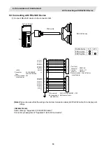
Page 78: ...27 cannot be turned ON immediately after it is turned OFF Wait at least 2 seconds and then turn the power ON 6 3 Connecting with Operation Panel I O Unit Connect operation panel I O unit to the connector OPI MITSUBISHI OPI G013 cable NC control unit Operation panel I O unit OPI Note When not using operation panel I O unit place terminator E TM on the OPI connector If nothing is connected to the OP...

Page 79: ...ectronics AMP manufacturer RIO1 RIO2 RIO3 FCUA R211 1 2 3 TXRX TXRX 0V 1 2 3 TXRX TXRX 0V FCUA R211 1 2 3 X FG FG 1 2 3 X FCUA R211 Note Connect to the FG terminal FG Note FG Note FG Note FG Note Max 8 stations Max 8 stations Related items Cable drawing Appendix 2 FCUA R211 cable Connector pin assignment Appendix 3 RIO connector 6 5 Connecting with Scan I O Card and Card sized I O Card Refer to th...

Page 80: ...00025 ENG MDS D SVJ3 SPJ3 Series Specifications Manual IB 1500158 ENG MDS D SVJ3 SPJ3 Series Instruction Manual IB 1500193 ENG MITSUBIS HI OPT1 G396 cable NC control unit Servo drive unit MDS D DH CN1A CN1B Servo drive unit MDS D DH CN1A CN1B Reinforced sheath G395 G380 cable OR Note 1 Binding the cables too tight with tie wraps could result in an increased loss or a disconnection Use a cushioning...

Page 81: ...tical communication cable POF type Core Plastic Application Use when wiring a cable of 10m or less inside the panel Min bending radius Cable Minimum bending radius 2 core parallel cord 30mm or more G395 Cable Wire material Optical communication cable POF type Core Plastic Application Use when wiring a cable of 10m or less outside the panel Min bending radius Cable Minimum bending radius 2 core cab...

Page 82: ... CT to the connector SV1 SV2 MITSUBISHI SV1 NC control unit Auxiliary axis servo drive unit MR J2 CT CN1A CN1B CN1A CN1B SV2 Auxiliary axis servo drive unit MR J2 CT CN1A CN1B CN1A CN1B SH21 cable SH21 cable Auxiliary axis servo drive unit MR J2 CT Auxiliary axis servo drive unit MR J2 CT Related items Cable drawing Appendix 2 SH21 Cable Connector pin assignment Appendix 3 SV1 connector SV2 connec...

Page 83: ... computer PC AT compatible RS 232C connector for configuration RS 232C cross cable To the FCU7 HN571 side CONF connector Dsub female connector 9pin To the PC side serial port Dsub female connector 9pin RXD TXD DTR GND RTS CTS 2 3 4 6 5 1 7 8 9 2 3 4 6 5 1 7 8 9 RXD TXD DTR DSR GND DCD RTS CTS RI Terminator slide switch PROFIBUS cable PROFIBUS DP communication connector FG terminal block PROFIBUS D...

Page 84: ...sion unit onto the right side of the control unit and then place an optical communication I F unit into the expansion unit slot There are two types of optical servo communication I F units available FCU7 HN551 For 1ch expansion FCU7 HN552 For 2ch expansion G380 cable PCF max20m or G395 G396 cable POF max10m Expansion unit FCU7 EX891 Optical servo communication I F unit 1ch expansion FCU7 HN551 2ch...

Page 85: ...A DB DG SLD FG DA FG SLD DG DB DA FG SLD DG DB FG Terminator Note 2 Terminator Note 2 Use either for wiring Note 3 NC side CC Link unit terminal block Remote I O station terminal block Remote I O station terminal block Shielded twisted cable with 3 wires Note 1 Shielded twisted cable with 3 wires Note 1 FG FG FG FG Note 1 Unless the CC Link dedicated cable is used CC Link system does not guarantee...

Page 86: ...lows to attach to the station Terminator Shorten the coated part Bend the lead wires Cut Cut 5 Insert the core wire into the opening of the terminal block Hold the wire tight with a flat blade screwdriver Check the screws on the terminal are loose enough before inserting the wires into the openings Flat blade driver Note 1 Do not solder plate the core wire which leads a defective cable contact Not...

Page 87: ...ded manufacturer Wire material UL1061 2464 AWG22 12P Recommended manufacturer Oki Electric Cable SIO 1ch FG 12 2 13 3 14 4 16 6 1 17 7 18 8 19 9 20 10 11 SD1 TXD1 RD1 RXD1 RS1 RTS1 CS1 CTS1 ER1 DTR1 DR1 DSR1 0V SD2 TXD2 RD2 RXD2 RS2 RTS2 CS2 CTS2 ER2 DTR2 DR2 DSR2 0V 2 3 4 5 20 6 8 9 7 2 3 4 5 20 6 8 9 7 2ch Hirose Electric HD LNA Reserved Reserved Reserved Reserved Note Please be aware that the w...

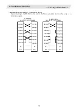
Page 88: ...the following diagrams and cross the wiring for the transmission signals SD TXD RD RXD RS RTS CS CTS ER DTR DR DSR CD DCD 0V FG No hand shaking upon RS CS ER DR signals Hand shaking upon RS CS ER DR signals SD TXD RD RXD RS RTS CS CTS ER DTR DR DSR CD DCD 0V FG SD TXD RD RXD RS RTS CS CTS ER DTR DR DSR CD DCD 0V FG SD TXD RD RXD RS RTS CS CTS ER DTR DR DSR CD DCD 0V FG ...

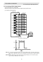
Page 89: ... SI4 SI5 SI6 SI7 FG 24VDC 0V Stabilized power supply 0V connection at COM terminal 1 5 11 15 COM 18 2 12 3 13 7 17 8 Control unit FG 2 2kΩ t Ton GND 24V Ton 2ms Note 1 NC recognizes input signals of 2ms or more as the valid skip signals If machine contacts relay etc are used malfunctions will occur due to chattering Use semiconductor contacts transistor etc Note 2 Fold the cable shield over the sh...

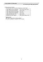
Page 90: ...ternal contact ON 18V or more 25 2V or less Input current at external contact ON 6mA or more Input voltage at external contact OFF 4V or less Input current at external contact OFF 2mA or less Input signal holding time Ton 2ms or more Machine side contact capacity 30V or more 16mA or more Related items Cable drawing Appendix 2 FCUA R030 cable Connector pin assignment Appendix 3 SKIP connector ...

Page 91: ... pulse generator When connecting two 5V manual pulse generators 5V 0V A B 5V 0V A B R050 cable R054 cable Synchronous feed encoder OSE1024 3 15 68 5V manual pulse generator Rear view ENC Related items Cable drawing Appendix 2 FCUA R050 R054 Cable G023 G024 Connector pin assignment Appendix 3 ENC connector Refer to the section 7 6 2 Connecting with 5V Manual Pulse Generator for 5V manual pulse gene...

Page 92: ...When not using control unit side emergency stop input signal such as when operation panel I O unit side emergency stop input signal EMG is used invalidate the input signal by using terminal cable G123 G123 cable comes with the control unit Connector 51030 0330 Contact 50084 8160 Recommended manufacturer Connector name G123 EMG NC control unit Bottom view EMG 1 2 3 24V EMGIN EMG MOLEX ...

Page 93: ...24V EMGIN Emergency stop input circuit 24V EMGIN LG R FG 1 2 3 Connector 51030 0330 Contact 50084 8160 Recommended manufacturer Connector name EMG MOLEX Note1 When installing emergency stop switch at operation panel and electric cabinet each both emergency stop input signals EMG the signal at the operating panel I O unit side and at the control unit side can be used Note2 Emergency stop is complia...

Page 94: ... EMG CN23A EMGIN CN23B Operation panel I O unit FCU7 DX EMGIN OPI OPI EMG EMGIN CG32 NC R Safety observing function provides the function compliant to the machinery directive in European Safety Standards The safety of this product is compliant to the safety category 3 of the European Safety Standards EN954 1 1996 However make sure to check the safety of the machine by using risk assessment With th...

Page 95: ...SDIO connector pin assignment Description of SDIO connector terminal Pin I O Function Pin I O Function 1A COM Sink common 24V Source common 0V 1B RG GND for DO 24V power supply 2A I SDI1 Door 1 switch input 2B I SDI2 Door 2 switch input 3A Reserved Not connected 3B Reserved Not connected 4A 24VDC DO power supply 4B O SDO1 Contactor control output 5A Reserved Not connected 5B Reserved Not connected...

Page 96: ...10 SDIO SDIO COM 1A 2A 3A 4A 5A 1B 2B 3B 4B 5B SDI2 SDI1 Reserved Connector 51353 1000 Contact 56134 9000 x6 Recommended manufacturer MOLEX Wire material UL1061 2464 AWG22 Recommended manufacturer Oki Electric Cable NC control unit Crimp terminal Recommended manufacturer Reserved 24V SDO1 Reserved Reserved 0V JST V1 25 3 Note This cable must be prepared by the machine tool builder ...

Page 97: ...d I O card scan I O card etc can be extended up to 5 channels Note that the following a and b will be applied if DI DO mounted on the operation panel I O unit is used a When 32 points 32 points are used up to 5 channels or 160 points 160 points in total are available b When 64 points 64 points are used up to 4 channels or 128 points 128 points in total are available 4 Manual pulse generator 3ch 5V...

Page 98: ...oard etc Machine control panel switchboard etc R211 cable R300 R301 cable R300 R301 cable Machine control panel switchboard etc R300 R301 cable Machine control panel switchboard etc R300 R301 cable 5V manual pulse generator F020 F021 F022 cable Keyboard unit G310 cable Emergency stop signal F120 cable 24VDC Stabilized power supply F070 cable LAN Display unit G301 cable G020 G021 G022 cable 12V man...

Page 99: ...it DCIN DCIN 2 178288 3 1 175218 5 Note Install the ferrite core that comes with the operation panel I O unit on the F070 cable Refer to the section Appendix 5 5 Ferrite Core Installation Method for details Related items Cable drawing Appendix 2 F070 cable Connector pin assignment Appendix 3 DCIN connector 2 Specifications of power supply When selecting the stabilized power supply prepared by mach...

Page 100: ...lay Unit Connect display unit to the connector PCLAN G301 cable 1m comes with the operation panel I O unit Operation panel I O unit PCLAN Display unit Rear view PCLAN LAN G301 cable LAN straight cable LAN Related items Cable drawing Appendix 2 G301 cable Connector pin assignment Appendix 3 LAN connector ...

Page 101: ...Keyboard Unit Connect keyboard unit to the connector NCRST G310 cable 10cm comes with the operation panel I O unit Operation panel I O unit NCRST NCRST NCRST G310 cable NCRST Keyboard unit Rear view Related items Cable drawing Appendix 2 G310 cable Connector pin assignment Appendix 3 NCRST connector ...

Page 102: ...ency stop input signal EMG When using operation panel I O unit side emergency stop input signal EMG use F120 cable to connect to the emergency stop switch F120 EMG Emergency stop switch EMG 1 2 3 FG 24V EMGIN 24V EMGIN LG R Emergency stop input circuit Operation panel I O unit FG 1 2 3 Recommended manufacturer MOLEX Connector name Contact Connector EMG 51030 0330 50084 8160 ...

Page 103: ... with the operation panel I O unit G123 EMG EMG 1 2 3 24V EMGIN Operation panel I O unit Recommended manufacturer MOLEX Connector name Contact Connector EMG 51030 0330 50084 8160 Note1 When installing emergency stop switch at operation panel and electric cabinet each both emergency stop input signals EMG the signal at the operating panel I O unit side and at the control unit side can be used Note2...

Page 104: ... 12V 0V A B 12V 0V A B 12V 0V A B 12V 0V A B 12V 0V A B MPG Operation panel I O unit 12V manual pulse generator input conditions 12V manual pulse generator input output circuit Input pulse signal type 90 phase difference between A and B Refer to waveform below Input signal voltage H level 3 5V to 5 25V L level 0V to 0 5V Max input pulse frequency 100kHz Power voltage for pulse generators 12VDC 10 ...

Page 105: ...ut pulse signal type 90 phase difference between A and B Refer to waveform below Input signal voltage H level 3 5V to 5 25V L level 0V to 0 5V Max input pulse frequency 100kHz Power voltage for pulse generators 5VDC 10 Max output current 100mA No of pulses per rotation 25 pulse rev or 100pulse rev T A B phase B A phase b d a c e 220Ω 470Ω 0V 5V 4700pF 1 3 5 2 4 6 7 8 9 11 13 220Ω 470Ω 0V 5V 4700pF...

Page 106: ...connecting channels and I O points Operation panel I O unit type Max No of channels RIO3 connection Max No of I O points RIO3 connection FCU7 DX670 5 channels 160 points 160 points FCU7 DX671 5 channels 160 points 160 points FCU7 DX770 4 channels 128 points 128 points FCU7 DX771 4 channels 128 points 128 points Note Refer to the section 8 2 Connecting with Remote I O Unit for the number of occupie...

Page 107: ...Series Refer to the section 7 9 3 Outline of Digital Signal Input Circuit 7 9 2 Wiring the Output Side DO Connector CG32 CG34 An insulation type DO output is used with the operation panel I O unit Effective in improving the resistance against noise from external sources So the DO output power is supplied from an external source and the wiring method on the machine side differs from that of M60 M60...

Page 108: ...e type share the digital signal input circuit Connect according to each respective diagram below COM Machine side A3 B3 Sink type CG31 CG33 0V RG 0V RG 0V RG 0V RG 0V RG 24VDC 2 2kΩ 2 2kΩ 2 2kΩ 2 2kΩ 2 2kΩ Control unit COM Machine side A3 B3 Source type CG31 CG33 0V RG 24VDC 2 2kΩ 2 2kΩ 2 2kΩ 2 2kΩ 2 2kΩ Control unit 24VDC 24VDC 24VDC 24VDC Input circuit ...

Page 109: ...nput voltage at external contact OFF 20V or more 25 2V or less 4V or less 4 Input current at external contact OFF 2mA or less 5 Tolerable chattering time 3ms or less Refer to T1 below 6 Input signal holding time 40ms or more Refer to T2 below 7 Input circuit operation delay time 3ms T3 T4 16ms 8 Machine side contact capacity 30V or more 16mA or more Note Input signal holding time 40ms or more as a...

Page 110: ... Insulation method Insulation Rated load voltage 24VDC Max output current 60mA point Output delay time 40µs Note 1 When using an inductive load such as a relay always connect a diode voltage resistance 100V or more 100mA or more in parallel to the load Note 2 When using a capacitive load such as a lamp always connect a protective resistor R 150Ω serially to the load to suppress rush currents Make ...

Page 111: ...Output device Connection example 20A 19A 18A 17A 16A 15A 14A 13A 12A 11A 10A 9A 8A 7A 6A 5A Y200 Y201 Y202 Y203 Y204 Y205 Y206 Y207 Y208 Y209 Y20A Y20B Y20C Y20D Y20E Y20F Y210 Y211 Y212 Y213 Y214 Y215 Y216 Y217 Y218 Y219 Y21A Y21B Y21C Y21D Y21E Y21F Note 1 Connect 24V to the flat connector 1B 2B 24VDC 1 Note 2 Connect 0V GND to the flat connector 3A 3B 4A 4B DOCOM 2 Note 3 Connect 0V GND to the ...

Page 112: ... 16A 15A 14A 13A 12A 11A 10A 9A 8A 7A 6A 5A Y200 Y201 Y202 Y203 Y204 Y205 Y206 Y207 Y208 Y209 Y20A Y20B Y20C Y20D Y20E Y20F Y210 Y211 Y212 Y213 Y214 Y215 Y216 Y217 Y218 Y219 Y21A Y21B Y21C Y21D Y21E Y21F Note 1 Connect 24V to the flat connector 1B 2B 24VDC 1 Note 2 Connect 24V to the flat connector 3A 3B 4A 4B DOCOM 1 Note 3 Connect 0V GND to the flat connector 1A 2A GND 2 Note 4 For the power sup...

Page 113: ...ction Detailed configuration 1 Remote I O Connecting with analog input analog output and manual pulse generator is possible besides DI DO Refer to 8 2 Refer to 2 3 5 2 Scan I O DI DO input output 32 32 is possible besides scan type Refer to 8 3 Refer to 2 3 6 3 Card sized I O 55mm x 93mm in size Connector PCB must be manufactured by the machine tool builder when using card size I O card Refer to 8...

Page 114: ...tion sink source type Digital output signal DO 32 points non insulation source type 1 FCUA DX110 Digital input signal DI 64 points photo coupler insulation sink source type Digital output signal DO 48 points non insulation sink type 2 FCUA DX111 Digital input signal DI 64 points photo coupler insulation sink source type Digital output signal DO 48 points non insulation source type 2 FCUA DX120 Dig...

Page 115: ...ion No changeover switch DO L machine output signal connector RIO1 serial connection connector 1 RIO2 serial connection connector 2 DCIN 24VDC power input connector DI R machine input signal connector DO R machine output signal connector AIO analog signal input output connector DS CS For changeover of transfer speed Normally set to left side Not used Selection of station No Enlarged view of DS and...

Page 116: ...upied serial link stations FCUA DX10 1 FCUA DX11 2 FCUA DX12 2 FCUA DX14 2 When using multiple remote I O units a characteristic station No must be set for each unit The FCUA DX10 unit has one station No setting switch and FCUA DX11 DX12 and DX14 unit have two switches Each of these switches must be set to a characteristic station No within a range of 0 to 7 Setting example 1 FCUA DX10 unit 0 Sett...

Page 117: ...of occupied stations 8 Maximum configuration 2 3 4 5 6 7 Control unit 0 No of occupied stations 2 1 MITSUBISHI No of occupied stations 2 No of occupied stations 2 No of occupied stations 2 Note The assignment of each unit s input output signal address will change with the setting of the channel No Refer to PLC Interface Manual for details ...

Page 118: ...re the digital signal input circuit Connect according to each respective diagram below COM Machine side A3 B3 Sink type DI L DI R 0V RG 0V RG 0V RG 0V RG 0V RG 24VDC 2 2kΩ 2 2kΩ 2 2kΩ 2 2kΩ 2 2kΩ Control unit COM Machine side A3 B3 Source type DI L DI R 0V RG 24VDC 2 2kΩ 2 2kΩ 2 2kΩ 2 2kΩ 2 2kΩ Control unit 24VDC 24VDC 24VDC 24VDC Input circuit ...

Page 119: ...age at external contact OFF 20V or more 25 2V or less 4V or less 4 Input current at external contact OFF 2mA or less 5 Tolerable chattering time 3ms or less Refer to T1 below 6 Input signal holding time 40ms or more Refer to T2 below 7 Input circuit operation delay time 3ms T3 T4 16ms 8 Machine side contact capacity 30V or more 16mA or more Note Input signal holding time 40ms or more as a guidelin...

Page 120: ...4VDC Max output current 60mA point Output delay time 40µs Note 1 When using an inductive load such as a relay always connect a diode voltage resistance 100V or more 100mA or more in parallel to the load Note 2 When using a capacitive load such as a lamp always connect a protective resistor R 150Ω serially to the load to suppress rush currents Make sure that the current is less than the above toler...

Page 121: ...nal Output Circuit The analog signal output circuit can be used only for the FCUA DX120 DX121 DX140 DX141 Output circuit DAC R R A0 A0 OV RG 220Ω Output conditions Output voltage 0V to 10V 5 Resolution 12bit 10V n 4096 Note Load conditions 10kΩ load resistance Output impedance 220Ω Note n 20 to 211 ...

Page 122: ...utline of Analog Signal Input Circuit The analog signal input circuit can be used only for the FCUA DX140 DX141 Input circuit ADC 150Ω AI AI OV RG Input conditions Max input rating 15V Resolution 10V 2000 5mV Precision Within 25mV AD input sampling time 14 2ms AI0 42 6ms AI1 to 3 ...

Page 123: ...I R and DO L DO R connectors The CS301 connector set optional with both ends includes the DI L and DO L connectors and two connectors for connection with the terminal block IDEC Note 1 IDEC I O terminal BX1F T40 24VDC 24VDC Machine control panel DI L FCUA DX100 140 COM A 3 B1 B2 A1 A2 B1 B2 A1 A2 2 2kΩ Input circuit Sink type Output circuit Sink type DO L 0V RG RA PL Control circuit Stabilized pow...

Page 124: ...5E X5F COM 0V RG 0V RG A DI L B Y40 Y41 Y42 Y43 Y44 Y45 Y46 Y47 Y48 Y49 Y4A Y4B Y4C Y4D Y4E Y4F 24VDC 24VDC B 20 19 18 17 16 15 14 13 12 11 10 9 8 7 6 5 4 3 2 1 A Y50 Y51 Y52 Y53 Y54 Y55 Y56 Y57 Y58 Y59 Y5A Y5B Y5C Y5D Y5E Y5F 0V RG 0V RG A DO L Control unit Operation panel I O unit R TM Remote I O unit Y DCIN 1 2 3 24V 0V FG RIO1 1 2 3 TxRx TxRx LG RIO2 1 2 3 TxRx TxRx LG X X Adaptive connector X...

Page 125: ...ted When manufacturing the R031 cable use the CS000 connector set optional with both ends AIO 1 10 11 20 Pin No R031 cable FCUA DX14 Input output circuit DAC 220Ω R R 150Ω ADC AI0 A0 FCUA DX14 7 GND Input Output Connector pin No GND GND GND AI1 AI2 AI3 13 12 2 3 150Ω 150Ω 150Ω 1 11 5 15 OV RG OV RG CAUTION Incorrect connections could damage the device so always connect the cable to the designated ...

Page 126: ... L DI R and DO L DO R connectors The CS301 connector set optional with both ends includes the DI L and DO L connectors and two connectors for connection with the terminal block IDEC Note 1 IDEC I O terminal BX1F T40 24VDC 24VDC Machine control panel DI L R FCUA DX110 COM A3 B3 B1 B2 A1 A2 B1 B2 A1 A2 2 2kΩ Input circuit Sink type Output circuit Sink type DO L R 0V RG RA PL Control circuit Stabiliz...

Page 127: ...C 24VDC B 20 19 18 17 16 15 14 13 12 11 10 9 8 7 6 5 4 3 2 1 A 0V RG 0V RG A DO R B Y40 Y41 Y42 Y43 Y44 Y45 Y46 Y47 Y48 Y49 Y4A Y4B Y4C Y4D Y4E Y4F 24VDC 24VDC B 20 19 18 17 16 15 14 13 12 11 10 9 8 7 6 5 4 3 2 1 A Y50 Y51 Y52 Y53 Y54 Y55 Y56 Y57 Y58 Y59 Y5A Y5B Y5C Y5D Y5E Y5F 0V RG 0V RG A DO L DI L 20 19 18 17 16 15 14 13 12 11 10 9 8 7 6 5 4 3 2 1 A X50 X51 X52 X53 X54 X55 X56 X57 X58 X59 X5A ...

Page 128: ...onnectors The CS301 connector set optional with both ends includes the DI L and DO L connectors and two connectors for connection with the terminal block IDEC Note 1 IDEC I O terminal BX1F T40 Outline of connection 24VDC 24VDC Machine control panel DI L R FCUA DX120 COM A3 B3 B1 B2 A1 A2 B1 B2 A1 A2 2 2kΩ Input circuit Sink type Output circuit Sink type DO L R 0V RG RA PL 24VDC COM A3 B3 B1 B2 A1 ...

Page 129: ... 24VDC B 20 19 18 17 16 15 14 13 12 11 10 9 8 7 6 5 4 3 2 1 A AO 0V 0V A DO R B Y40 Y41 Y42 Y43 Y44 Y45 Y46 Y47 Y48 Y49 Y4A Y4B Y4C Y4D Y4E Y4F 24VDC 24VDC B 20 19 18 17 16 15 14 13 12 11 10 9 8 7 6 5 4 3 2 1 A Y50 Y51 Y52 Y53 Y54 Y55 Y56 Y57 Y58 Y59 Y5A Y5B Y5C Y5D Y5E Y5F 0V 0V A DO L DI L 20 19 18 17 16 15 14 13 12 11 10 9 8 7 6 5 4 3 2 1 A X50 X51 X52 X53 X54 X55 X56 X57 X58 X59 X5A X5B X5C X5...

Page 130: ...he R031 cable must be manufactured by the user Note 1 IDEC I O terminal BX1F T40A RA PL Machine control panel electric cabinet etc R300 cable R301 cable IDEC BX1F T40A 15 13 9 11 7 5 3 1 31 29 25 27 23 21 19 17 33 35 37 39 16 14 10 12 8 6 4 2 32 30 26 28 24 22 20 18 34 36 38 40 Connector pin correspondence table Terminal block BX1F FCUA DX1 2 B1 4 B2 6 B3 8 B4 10 B5 12 B6 14 B7 16 B8 18 B9 20 B10 ...

Page 131: ...mA point Scan Output Output cycle 1 46ms cycle 5 84ms cycle No of points 32 points Type Sink source Input voltage at external contact ON 6V or less 18V or more 25 2V or less Input current at external contact ON 2mA or less 9mA or more Input voltage at external contact OFF 20V or more 25 2V or less 4V or less Input current at external contact OFF 9mA or more 2mA or less Tolerable chattering time 2 ...

Page 132: ...ections of I O Interface 8 3 Connecting with Scan I O Card 113 8 3 2 Hardware Interface 1 Connector layout diagram 0 0 0 HR347 357 Scan DI DO 64 64 A B 25 1 DIO SCAN2 SCAN1 RIO3 DCIN B A DI 32 D0 32 CF33 CF31 ...

Page 133: ...14 O Y56 13 O Y47 13 O Y57 12 O Y48 12 O Y58 11 O Y49 11 O Y59 10 O Y4A 10 O Y5A 9 O Y4B 9 O Y5B 8 O Y4C 8 O Y5C 7 O Y4D 7 O Y5D 6 O Y4E 6 O Y5E 5 O Y4F 5 O Y5F 4 4 3 3 2 I 24VDC 2 0V RG 1 I 24VDC 1 0V RG CF33 DIO 2 Cable side connector type Connector 7940 6500SC Relief 3448 7940 Recommended manufacturer 3M This example shows SCAN1 set to 0 SCAN2 set to 1 and DIO set to 2 Refer to PLC Interface Ma...

Page 134: ... 9 O KYC7 9 O KYC6 8 O KYC5 8 O KYC4 7 O KYC3 7 O KYC2 6 O KYC1 6 O KYC0 5 I KYD7 5 I KYD6 4 I KYD5 4 I KYD4 3 I KYD3 3 I KYD2 2 I KYD1 2 I KYD0 1 1 GND CF35 Note The GND pin is not normally used Do not connect the GND pin to the frame ground Cable side connector type Connector 7950 6500SC Relief 3448 7950 Recommended manufacturer 3M SCAN1 0 2 SCAN2 This example shows SCAN1 set to 0 SCAN2 set to 1...

Page 135: ...s Set using SCAN1 SCAN 2 and DIO rotary switches The assignment address is changed with the rotary switch setting 0 0 0 Standard setting SCAN1 0 SCAN2 1 DIO 2 CF35 SCAN1 SCAN2 DIO Scan DI 32 Scan DO 32 Scan DO 32 Scan DI 32 Address X00 X1F Address X20 X3F Address Y00 Y1F Address Y20 Y3F CF31 CF33 Digital DI 32 Address X40 Digital DO 32 Address Y40 ...

Page 136: ...I O communication cable RIO3A B a Connection of the RIO3A connector Connect the RIO3A to the RIO1 RIO2 connector of the control unit or the RIO3 of the operation panel I O unit RIO1 R211 RIO3 HR357 A Control unit b Connection of the RIO3B connector When the remote I O unit is connected with a serial link multiple units can be combined and used in a range of eight or less total occupied stations Re...

Page 137: ...11 X19 X21 X29 X31 X39 X00 X08 X10 X18 X20 X28 X30 X38 Example of a circuit manufactured by the machine tool builder Note To scan input connect a sneak path prevention diode as shown in the following drawing The unit may not be able to read the correct input signals without a sneak path prevention diode installed KYCO to KYC7 KYDO to KYD7 Sneak path prevention diode The common signals are changed ...

Page 138: ...Y20 Y21 Y22 Y23 Y24 Y25 Y26 Y27 Y28 Y29 Y2A Y2B Y2C Y2D Y2E Y2F Y30 Y31 Y32 Y33 Y34 Y35 Y36 Y37 Y38 Y39 Y3A Y3B Y3C Y3D Y3E Y3F Example of a circuit manufacturerd by the machine tool builder Example of a circuit manufacturerd by the machine tool builder Output circuit Manufactured by the machine tool builder CF35 5V LCnA B LDnA B 330Ω 0V RG HR3 7 The common signals are changed over with scan outpu...

Page 139: ... contact ON 6V or less 18V or more 25 2V or less 2 Input current at external contact ON 9mA or more 3 Input voltage at external contact OFF 20V or more 25 2V or less 4V or less 4 Input current at external contact OFF 2mA or less 5 Tolerable chattering time 3ms or less Refer to T1 below 6 Input signal holding time 40ms or more Refer to T2 below 7 Input circuit operation delay time 3ms T3 T4 16ms 8 ...

Page 140: ... damage etc Output conditions Insulation method Non insulation Rated load voltage 24VDC Max output current 60mA point Saturation voltage 1 6V standard Output delay time 40µs Note 1 When using an inductive load such as a relay always connect a diode voltage resistance 100V or more 100mA or more in parallel to the load Note 2 When using a capacitive load such as a lamp always connect a protective re...

Page 141: ...onnection Example An example of card sized I O card connection is shown below Card sized I O card is connected to the operation panel I O unit or control unit via the card sized I O card connector PCB Card sized I O card connector PCB must be manufactured by the machine tool builder Connection example Operation panel I O unit OPI OPI RIO3 Card sized I O card Operation board I O DI DO DI DO DI DO C...

Page 142: ...ote Sink type Source type Outline dimension 55mm x 93mm Connector in use 7650 5002SC Sumitomo 3M 50 pin Recommended connector 9150 4500SC Connector PCB side Sumitomo 3M 50 pin Note The input and output share the same type 2 Setting the channel No Channel No of the card sized I O card is set with CF30 of the card sized I O card connector PCB Connect the signal pin to 5VDC or GND according to the ch...

Page 143: ...es the total output current of the 24VDC output Refer to Appendix 8 Precautions for Compliance to UL c UL Standards as well 4 Connector pin assignment HR361 HR371 CF30 A B 1 GND 1 GND 2 I O TXRX 2 I O TXRX 3 I SEL1 3 I SEL2 4 I SEL3 4 I 24VDC 5 I 24VDC 5 I 24VDC 6 GND 6 GND 7 O YF 7 O Y7 8 O YE 8 O Y6 9 O YD 9 O Y5 10 O YC 10 O Y4 11 O YB 11 O Y3 12 O YA 12 O Y2 13 O Y9 13 O Y1 14 O Y8 14 O Y0 15 ...

Page 144: ...0 2 2kΩ 2 2kΩ GND Control circuit Sink type Source type No COM pin is available used only for input it is shared with 24VDC or GND CAUTION Do not apply voltages to the connectors other than voltages indicated in this manual Failure to observe this could cause the devices to rupture or damage etc Incorrect connections could cause the devices to damage Connect the cable to the designated connector D...

Page 145: ...less 4V or less Input current when external contact is OFF 9mA or more 2mA or less Tolerable chattering time T1 3ms or less Input signal hold time T2 40ms or more 1 Input circuit operation delay time 3ms T3 T4 20ms Machine side contact capacity 30V or more 16mA or more 1 Input signal hold time 40ms or more is the guideline and if not held for longer than the ladder processing cycle time the input ...

Page 146: ...ect connections could cause the devices to damage Connect the cable to the designated connector Do not connect or disconnect the connection cables between each unit while the power is ON d Output conditions HR361 HR371 Output current 60mA point Saturated voltage 1 6V standard Output delay time 40μs Note 1 When using an inductive load such as relay always connect a diode withstand voltage 100V or m...

Page 147: ... AI x 4ch No of output points AO x 1ch AO x 1ch Outline dimension 55mm x 93mm Connector in use 7650 5002SC Sumitomo 3M 50 pin Recommended connector 9150 4500SC Connector PCB side Sumitomo 3M 50 pin 2 Setting the channel No Channel No of the card sized I O card is set with CF30 of the card sized I O card connector PCB Connect the signal pin to 5VDC or GND according to the chart below The card sized...

Page 148: ...erve 12 reserve 12 reserve 13 reserve 13 reserve 14 reserve 14 O AO0 15 GND 15 GND 16 reserve 16 reserve 17 reserve 17 reserve 18 reserve 18 reserve 19 reserve 19 reserve 20 GND 20 reserve 21 GND 21 reserve 22 GND 22 reserve 23 GND 23 reserve 24 GND 24 GND 25 I 5VDC 25 I 5VDC HR383 CF36 A B 1 GND 1 GND 2 I O TXRX 2 I O TXRX 3 I SEL1 3 I SEL2 4 I SEL3 4 reserve 5 reserve 5 reserve 6 GND 6 GND 7 res...

Page 149: ...ms AI0 42 6ms AI1 to 3 c Output conditions Output voltage 10V to 10V 5 Resolution 12bit 10V x n 4096 n 20 to 211 Load conditions 10kΩ load resistance Output impedance 220Ω CAUTION Do not apply voltages to the connectors other than voltages indicated in this manual Failure to observe this could cause the devices to rupture or damage etc Incorrect connections could cause the devices to damage Connec...

Page 150: ... terminator 100Ω 1 1 4W RN14C2E101F Koa Denko Example When four connectors are installed on the card sized I O card connector PCB TXRX TXRX B2 A2 100Ω NC control unit RIO1 2 3 Connector CF30 CF36 on card sized I O card connector PCB 2 Shield treatment of communication signal cable Because the card sized I O card communication cables TXRX TXRX communicate at a high speed they must be wired separate...

Page 151: ...he direction as shown in installation 1 or installation 2 below Top Installation 1 Bottom Top Installation 2 Bottom Note If the card sized I O card is installed horizontally the heat will build up So do not install the card as shown below Top Bottom 4 Installation spacing The card sized I O card installation spacing must be 15mm or more ...

Page 152: ...the remote I O communication of the operation panel I O unit remote I O communication or communication terminal remote I O communication MC link B Compatible machine control signals No of occupied stations Digital input signal DI 64 points photocoupler insulation sink source shared type Digital output signal DO 48 points non insulation source type 2 8 5 2 Hardware Interface 1 Connector layout diag...

Page 153: ...tact MRP F102 Case MR20W Recommended manufacturer HONDA TSUSHIN KOGYO CMD81 18 1 33 50 Cable side connector type Connector MRP50F01 Contact MRP F102 Case MR50W Recommended manufacturer HONDA TSUSHIN KOGYO 7 0V RG 13 20 DC24V 6 12 X36 19 X37 5 X35 11 X33 18 X34 4 X32 10 X30 17 X31 3 X3F 9 X3D 16 X3E 2 X3C 8 X3A 15 X3B 1 X39 14 X38 CMD82 18 0V RG 50 X27 17 X26 49 X25 16 X24 32 X22 48 X23 15 X21 31 X...

Page 154: ... 0 Refer to PLC Interface Manual for details 3 Rotary switch Set the address station No assignment for two stations in DI DO 64 48 point units Set using the CS1 rotary switch The assignment address is changed with the rotary switch setting CS1 Setting Function 0 Remote I O station 0 1 station selection 1 Invalid 2 Remote I O station 2 3 station selection 3 Invalid 4 Remote I O station 4 5 station ...

Page 155: ...e rated output current is the value when using 60mA 48 points for the machine output DO Prepare a power supply that satisfies the 24VDC output s total output current Note Cables for the J4 connector must be manufactured by the machine tool builder 2 Remote I O connections CSH41A B a Connection of the CSH41A connector Connect the CSH41A connector to the RIO1 RIO2 connector of the control unit or RI...

Page 156: ... output and source type input circuit corresponding to the machine side source output Sink type Source type Machine side Machine side 24VDC 24VDC 0V RG 0V RG 0V RG QY231 QY231 2 2kΩ 2 2kΩ 2 2kΩ 2 2kΩ CMD81 82 CMD81 82 COM COM Control circuit Control circuit CAUTION Do not apply any voltage to the connector other than that specified in this manual Failure to observe this could cause bursting damage...

Page 157: ...ternal contact OFF 20V or more 25 2V or less 4V or less 4 Input current at external contact OFF 2mA or less 5 Tolerable chattering time 3ms or less Refer to T1 below 6 Input signal holding time 40ms or more Refer to T2 below 7 Input circuit operation delay time 3ms T3 T4 16ms 8 Machine side contact capacity 30V or more 16mA or more Note Input signal holding time 40ms or more as a guideline The inp...

Page 158: ...ng damage etc Output conditions Insulation method Non insulation Rated load voltage 24VDC Max output current 60mA point Saturation voltage 1 6V standard Output delay time 40µs Note 1 When using an inductive load such as a relay always connect a diode voltage resistance 100V or more 100mA or more in parallel to the load Note 2 When using a capacitive load such as a lamp always connect a protective ...

Page 159: ...ons Refer to the section 8 2 Connecting with Remote I O Unit for details QY231 occupies two stations so the remote I O units including this card can be connected to RIO1 of the control unit in combinations of 6 stations or less Connect a terminator R TM to the CSH41B when it is not connected to any device CS1 SW1 J4 CMD81 CFD83 CMD82 CSH41A CSH41B SOURCE SINK S1 S2 S3 S4 QY231 Terminator optional ...

Page 160: ... USB device Ver1 1 USB cable RS 232C device G031 G032 cable G291 cable 24VDC stabilized power supply F070 cable USB Keyboard unit G290 cable Front IC card I F unit Menu key G093 cable LCD F480 cable Inverter PCB CF ATA mode Note The following cables come with each unit G290 cable 0 7m G291 cable 0 1m G093 cable F480 cable G301 cable 1m LAN USB1 USB2 SIO FRONTOUT MENUKEY LCD INV CF DCIN Note When c...

Page 161: ...480 cable Inverter PCB CF IDE mode F130 cable FDD unit F140 cable HDD unit Not used HDD heater power supply I F G170 cable ON OFF switch G171 cable Note The following cables come with each unit G290 cable 0 7m G291 cable 0 1m G093 cable F480 cable G301 cable 1m LAN USB1 USB2 SIOPC FRONTOUT MENUKEY LCD INV CF DCIN CF01 CF24 ON OFF FDD HDD CF25 PD25 PD27 power supply unit ON OFF Note When connecting...

Page 162: ...of display unit power supply to be connected differs Display unit Power supply FCU7 DA2 General purpose 24VDC stabilized power supply or PD25 PD27 power supply unit FCU7 DA3 FCU7 DA4 PD25 PD27 power supply unit Note Controlling with ACFAIL signal is necessary therefore general purpose stabilized power supply cannot be used ...

Page 163: ...h current so be careful When 24VDC s ON OFF are directly controlled by a magnetic switch such as relay AND When heat capacity of the contacts for relay etc used to control 24VDC s ON OFF is small 2 Specifications of power supply When selecting the stabilized power supply prepared by machine tool builder consider the characteristics indicated in the section 6 2 1 When Using General Purpose 24VDC St...

Page 164: ...ately after it is turned OFF Wait at least 2 seconds and then turn the power ON Related items Cable drawing Appendix 2 F110 cable F170 cable Connector pin assignment Appendix 3 DCIN connector CF01 connector 2 Specifications of PD25 PD27 power supply Refer to the section 6 2 2 When Using PD25 PD27 Power Supply Unit for details on PD25 PD27 CAUTION Do not apply voltages to the connectors other than ...

Page 165: ...OFF Wait at least 2 seconds and then turn the power ON Related items Cable drawing Appendix 2 F110 cable G170 cable G171 cable Connector pin assignment Appendix 3 DCIN connector CF01 connector CF24 connector ON OFF connector 2 Specifications of PD25 PD27 power supply Refer to the section 6 2 2 When Using PD25 PD27 Power Supply Unit for details on PD25 PD27 CAUTION Do not apply voltages to the conn...

Page 166: ...t Rear view USB1 USB USB1 Ferrite Note Do not use commercially available USB cable Failure to observe could result in malfunction Related items Connector pin assignment Appendix 3 USB connector CAUTION Do not apply voltages to the connectors other than voltages indicated in this manual Failure to observe this could cause the devices to rupture or damage etc Incorrect connections could cause the de...

Page 167: ...r view CN1 FRONTOUT CN1 FRONT OUT Related items Cable drawing Appendix 2 G291 cable Connector pin assignment Appendix 3 FRONTOUT CAUTION Do not apply voltages to the connectors other than voltages indicated in this manual Failure to observe this could cause the devices to rupture or damage etc Incorrect connections could cause the devices to damage Connect the cable to the designated connector Do ...

Page 168: ...D001 Note 2 Do not turn the power OFF during access to the hard disk Failure to observe this could cause the units to malfunction In case of emergency always perform backups by having your important data duplicated etc as MITSUBISHI will not guarantee the broken or lost data Be sure to inform this matter to the end users Related items Cable drawing Appendix 2 F140 cable Connector pin assignment Ap...

Page 169: ...ble comes with the floppy disk unit FCU7 FD221 1 Display unit Rear view F130 cable Floppy disk unit FDD FRONT OUT FDD F01 F02 Related items Cable drawing Appendix 2 F130 cable Connector pin assignment Appendix 3 FDD connector When connecting F130 cable with the floppy disk unit arrange so that the PCB side is the bottom and the connector incorrect insertion prevention key is placed facing upward F...

Page 170: ... suitable for FA environment for temperature or noise wise In the case of using it careful performance check must be required by the machine tool builder Note 3 Do not pull out the floppy disk or turn OFF the power during access to the floppy disk Failure to observe this could cause the memory contents to be erased In case of emergency always perform backups by having your important data duplicate...

Page 171: ... L21 CN3 CN1A CN4 CN9 CN20 CN1B MU MV MW CN2L CN2M LU LV LW TE1 Motor side detector Motor side detector Servo drive unit Servo motor Servo motor Machine side detector Machine side detector TE3 TE2 L L L11 L21 Ground CN3L CN3M Breaker Optical communication cable Optical communication cable MC1 CN23B SH21 cable EMG1 EMG2 24VDC MC Note 1 The total length of the optical communication cable from the NC...

Page 172: ...le Optical communication cable P Regenerative resistor unit C P Regenerative resistor unit C L1 L2 L3 L11 L21 Spindle motor Servo motor T S R Breaker Contactor Breaker CNP2 CNP1 CNP2 CNP3 CNP2 CNP1 CNP2 CNP3 Spindle side detector T S R Breaker Breaker Contactor Note 1 The total length of the optical communication cable from the NC must be within 30m and the minimum bending radius within 80mm Note ...

Page 173: ...it for both the control unit and display unit b c a b a The switch is turned OFF b A signal is input from the OFF switch through the G170 cable which starts a shutdown process After the completion of the shutdown process the OFF signal is sent to PD27 through G171 cable c PD27 stops outputting the voltage Both display and control units are turned OFF a To stop the NC operations at the same time of...

Page 174: ...put from the OFF switch through the G170 cable which starts a shutdown process After the completion of the shutdown process the OFF signal is sent to PD25 through G171 cable c PD25 stops outputting the voltage Relays operate to turn OFF the other power source Both display and control units are turned OFF a To stop the NC operations at the same time of switching OFF the display unit in order to kee...

Page 175: ...ity to prevent output of obstructive noise that adversely affects external devices Immunity Capacity to not malfunction due to obstructive noise from external source The details of each level are classified in the table below It is assumed that the Standards and test details required for a machine tool are the same as these Class Name Details EN Standards Emission Radiated noise Restriction of ele...

Page 176: ... a very important factor for the EMC measures so take the following measures into consideration 1 4 1 Measures for Control Panel Body 1 Use metal for all members configuring the panel 2 When joining the metal plate treat the welded or contacting sections so that the impedance is reduced and then fix with screws Painting mask Joining clearance Approx 20cm 3 Note that if the plate warps due to the s...

Page 177: ... impedance Note 2 Using screws to fix the plates that have been painted attachment of packing is the same as an insulated state Peel the paint and fix the screws 1 4 3 Measures for Power Supply 1 Shield the power supply section and insert a filter to prevent the noise from flowing in or out Selection of the noise filter capacity will differ according to the drive unit and devices being used Refer ...

Page 178: ... If the cables are led unnecessary in the panel they will pick up noise Pay attention to the device layout and wire length so that the wiring length is as short as possible Noise Device Device Device Device Device Device 2 Always connect the grounding wire to the FG terminal indicated on the device 3 Keep the distance between the drive line and detector cable to the drive section motor as far apar...

Page 179: ...ll a ferrite core on both ends of the connected units Always install a ferrite core on the general purpose stabilized power supply Refer to Appendix 1 6 2 Ferrite core The ferrite core may not be required depending on the selected power supply 2 Remote I O cable FCUA R211 cable Control panel Remote I O unit FCUA R211 cable Shield clamp Ferrite core Control panel Control unit Use a shield clamp wit...

Page 180: ...vide sufficient frame ground install the grounding plate directly on the cabinet or connect with a grounding wire Clamp section drawing Peel off the cable sheath at the clamp section Grounding plate Cable Shield sheath Clamp fitting Fitting A B Cable 40 1 6 2 Ferrite Core The ferrite core is mounted integrally with the plastic case This can be installed with one touch without cutting the interface...

Page 181: ... USB 7 ZCAT1730 0730A M BK 30 1 23 1 7 1 16 5 1 15 1 4 to 7 USB 12 ZCAT2035 0930A M BK 1 35 1 28 1 9 1 19 5 1 17 4 1 6 to 9 22 ZCAT2035 0930A BK 35 1 28 1 9 1 19 5 1 17 4 1 6 to 9 22 ZCAT2235 1030A M BK 35 1 28 1 10 1 21 5 1 20 1 8 to 10 27 ZCAT2436 1330A M BK 36 1 29 1 13 1 23 5 1 22 1 10 to 13 29 ZCAT2017 0930B M BK 21 1 17 1 9 1 20 1 28 5 1 9max 12 ZCAT2749 0430C M BK 49 1 27 1 4 5 1 19 5 1 4 5...

Page 182: ...it voltage 50 60Hz Vrms Max tolerable circuit voltage Clamp voltage V 10 Surge withstand level 8 20μs Surge electrical discharge start voltage 1 2 50μs Static capacity Working temperature range 250V 3φ 300V 783V 2500A 20kV 75pF 20 70 C 41 1 UL 1015 AW G16 Outline drawing a Black b Black c Black Circuit drawing Unit mm 2 Part name RAV 781BXZ 4 Manufacturer OKAYA ELECTRIC INDUSTRIES Circuit voltage ...

Page 183: ... absorbing effect as shown with the bold lines in the installation example above Wire material Diameter 2mm2 or more Wire length Length of wire connected to surge absorber a A is 2m or less Length of wire connected to surge absorber b B is 2m or less Length of wire connected to surge absorber b C is 2m or less 2 When carrying out the insulation withstand voltage test on the power supply line the s...

Page 184: ...s given below Stabilized power supply selection items Item Standard setting Remarks Voltage fluctuation 5 5 or less of 24VDC output Ripple noise 120mV max Output Spike noise 500mV max Output current Refer to the maximum current consumption of the unit in use and calculate Output holding time 20ms min Instantaneous power failure time AC side Standards Safety Standards UL1950 CSA C22 2 No 234 approv...

Page 185: ...ulse generator 1ch 20m 1 2 3 5 8 10 15 20 G024 Manual pulse generator 2ch 20m 1 2 3 5 8 10 15 20 Connect to control unit 5V power supply type can be used FCUA R030 Skip input 20m 3 7 Connect to control unit FCUA R031 Analog input output 20m 3 7 Connect to remote I O unit G031 RS 232C 1ch 15m 0 5 1 2 3 5 7 10 15 Connect to display unit G032 RS 232C 2ch 15m 0 5 1 2 3 5 7 10 15 Connect to display uni...

Page 186: ...o communication 20m 5 10 13 15 20 PCF type with outer sheath for panel external wiring G395 Optical servo communication 10m 1 2 3 5 10 POF type with outer sheath for panel external wiring G396 Optical servo communication 10m 0 3 0 5 1 2 3 5 10 POF type without outer sheath for panel internal wiring G430 Handy terminal 10m 3 5 10 Use for connecting a handy terminal Install on panel SH21 Servo commu...

Page 187: ...shield over the sheath and w rap copper foil tape over it Connect the w ound copper foil tape to the connector s GND plate Note 2 2 G015 Cable Cable type G015 cable Application I O interface OPIEXT Plug CDB 25P Recommended manufacturer Hirose Electric Connector name OPI Operation panel I O unit 1 2 5 6 9 10 11 12 14 15 18 19 20 21 1 11 3 13 5 15 6 16 7 17 9 19 10 20 0V 0V CMTT CMTR 0V 0V LANTD LAN...

Page 188: ...MPG Crimp terminal V1 25 3x12 Recommended manufacturer JST Wire material Recommended manufacturer Note Fold the cable shield over the sheath and wrap copper foil tape over it Connect the wound copper foil tape to the connector s GND plate 2ch 3ch 1ch Cable name F020 cable F021 cable F022 cable 2ch 3ch Precautions The circles indicate the used channel 1 2 10 9 3 4 12 11 5 6 14 13 1HA 1HB 12V 0V 2HA...

Page 189: ...Cable name G020 cable G021 cable G022 cable 2ch 3ch Precautions The circles indicate the used channel B 22 19 U x 2SJ 1 x 9 Sumitomo Electric Industries 2 5 G023 G024 Cable Cable type G023 G024 cable Application Manual pulse generator 5V power supply type ENC Connector 10120 3000VE Case 10320 52F0 008 Recommended manufacturer 3M Wire material UL1061 2464 AWG24 x 6P Recommended manufacturer Oki Ele...

Page 190: ...SKIP0 SKIP1 SKIP2 SKIP3 GND GND SKIP4 SKIP5 SKIP6 SKIP7 Control unit SKIP Connector 10120 3000VE Case 10320 52F0 008 Recommended manufacturer 3M Wire material UL1061 2464 AWG22 x 6P Recommended manufacturer Oki Electric Cable Crimp terminal V1 25 4 x 12 Recommended manufacturer JST Note Fold the cable shield over the sheath and wrap copper foil tape over it Connect the wound copper foil tape to th...

Page 191: ...ase 10320 52F0 008 Recommended manufacturer 3M Wire material UL1061 2464 AWG24 x 6P Recommended manufacturer Oki Electric Cable Crimp terminal V1 25 3 x 10 Recommended manufacturer JST Fold the cable shield over the sheath and wrap copper foil tape over it Connect the wound copper foil tape to the connector s GND plate Control unit FCUA DX14 7 GND AI1 GND AI2 GND AI3 GND AO GND Note ...

Page 192: ...nt to the generic names 3 Connect to the serial communication connector of the display unit Use F034 G035 cable when connecting to the serial communication connector of the control unit Note Fold the cable shield over the sheath and wrap copper foil tape over it Connect the wound copper foil tape to the connector s GND plate SIOPC Connector 10120 3000VE 10120 6000EL Case 10320 52F0 008 10320 3210 ...

Page 193: ...eses are equivalent to the generic names 3 Connect to the serial communication connector of the control unit Use G031 G032 cable when connecting to the serial communication connector of the display unit Note Fold the cable shield over the sheath and wrap copper foil tape over it Connect the wound copper foil tape to the connector s GND plate SIO Connector 10120 3000VE Case 10320 52F0 008 Recommend...

Page 194: ...20 29S Cable clamp MS3057 12A Recommended manufacturer ITT Cannon Connector MS3108B20 29S Cable clamp MS3057 12A Recommended manufacturer ITT Cannon Wire material UL1061 2464 AWG24 12P Recommended manufacturer Oki Electric Cable Connector name ENG ENC1 Plug 10120 3000VL Shell 10320 52F0 008 Recommended manufacturer 3M FCUA R050 cable FCUA R054 cable Note Fold the cable shield over the sheath and w...

Page 195: ...2 F110 Cable Cable type F110 cable Application 24VDC input power OFF detection Y 24V 0V FG ACFAIL 0V 1B 2B 3B 1A 2A 1 2 3 2 1 24V 0V FG ACFAIL 0V AWG16 AWG22 DCOUT DCIN CF01 Connector name DCOUT Connector name DCIN Connector name CF01 Connector 51030 0230 Cotact 50084 8160 x 2 Recommended maker MOLEX Wire material UL2464 2 x 22AWG 2 x 16AWG SS 95138 Recommended manufacturer DDK Connector 3 178127 ...

Page 196: ...ufacturer Sumitomo Electric Industries 1 2 3 FG EMG IN COM Crimp terminal V1 25 3 x 2 Recommended manufacturer JST EMG IN COM B22 9 2 14 G123 Cable Cable type G123 cable Application Emergency stop terminator Connector 51030 0330 Cotact 50084 8160 x 2 Recommended manufacturer MOLEX Connector name EMG Wire material B 22 19 U x 2SJ 1 x 9 Recommended manufacturer Sumitomo Electric Industries Circuit d...

Page 197: ...10A 11A 12A 13A 14A 15A 16A 17A 1B 3B 4B 5B 6B 7B 8B 9B 10B 11B 12B 13B 14B 15B 16B 17B 2A 2B 17B 15B 14B 13B 12B 11B 10B 9B 8B 7B 6B 5B 4B 3B 2B 1B 17A 15A 14A 13A 12A 11A 10A 9A 8A 7A 6A 5A 4A 3A 2A 1A Wire material AWG28 x 20P Recommended manufacturer Oki Electric Cable FDD FD1 1 2 3 4 FD2 FD1 Connector 7934 6500SC Strain relief 3448 7934 Recommended manufacturer 3M FD2 Connector 171822 4 Conta...

Page 198: ...7A 17B 18A 18B 19A 19B 20A 20B 21A 21B 22A 22B 23A 23B 24A 24B 25A 25B W ire materal specification UL2651 AW G28 HDD HDD Connector FCN 727B044 G LM D Recommended manufacturer FUJITSU 1A 1B 2A 2B 3A 3B 4A 4B 5A 5B 6A 6B 7A 7B 8A 8B 9A 9B 10A 10B 11A 11B 12A 12B 13A 13B 14A 14B 15A 15B 16A 16B 17A 17B 18A 18B 19A 19B 20A 20B 21A 21B 22A 22B Control unit Insert incorrect insertion prevention pin in 3...

Page 199: ...l 110 x 4 LGON ON LGOFF OFF ON OFF LGOFF LGON 1 2 3 4 2 18 G171 Cable Cable type G170 cable Application Power supply ON OFF CF24 Connector 51030 0530 Contact 50084 8160 x 4 Recommended manufacturer MOLEX CF24 Wire material DPVVSB 6P x 0 2SQ Recommended manufacturer Bando Electric Wire 1 2 3 4 5 N C P OFF 0V 0V P ON Connector name CF24 ON OFF Connector 1 178288 5 Contact 1 175218 5 x 4 Recommended ...

Page 200: ...d external power supply you use 2 20 FCUA R211 Cable Cable type FCUA R211 cable Application Remote I O Connector 1 178288 3 Contact 1 175218 2 x 3 Recommended manufacturer Tyco Electronics AMP RIO1 RIO2 RIO3 FCUA R211 Wire material MVVS 3C x 0 5mm2 MIC 3C x 0 5mm2 Recommended manufacturer Takeuchi Densen 1 2 3 TXRX TXRX 0V Connector name RIO1 RIO2 RIO3 FCUA R211 1 2 3 TXRX TXRX 0V Connector name F...

Page 201: ...act 50011 8100 x6 Recommended manufacturer MOLEX PCUSB Wire material DPVVSB 3P x 0 2SQ 6 2 3 4 5 N C USBD USBD GND SENSR Connector name PCUSB PCUSB Connector name PCUSB 6 2 3 4 5 1 1 5V N C USBD USBD GND SENSR 5V PCUSB Connector 51004 0600 Contact 50011 8100 x6 Recommended manufacturer MOLEX Recommended manufacturer Bando Electric Wire ...

Page 202: ...ire material LAN category 5 twisted pair x 4P White Green Green White Orange Orange Blue White Blue White Brown Brown 2 23 G301 Cable Cable type G301 cable Application LAN straight cable G301 LAN LAN 1 8 LAN LAN TD 1 2 3 6 4 5 7 8 1 2 3 6 4 5 7 8 RD TD RD RD TD RD TD CMTR CMTR CMTT CMTT CMTR CMTR CMTT CMTT White Green Green White Orange Orange Blue White Blue White Brown Brown LAN Connector 5 5585...

Page 203: ...nded manufacturer 3M Wire material B40 S Recommended manufacturer Oki Electric Cable 2 25 R301 Cable Cable type R301 cable Application DI DO cable Double side connector available Connector name DI L DO L DI R DO R Connector 7940 6500SC Recommended manufacturer 3M Connector 7940 6500SC Strain relief 3448 7940 Recommended manufacturer 3M Wire material B40 S Recommended manufacturer Oki Electric Cabl...

Page 204: ...er Japan Aviation Electronics Connector name OPT OPT Connector CF 2D103 S Recommended manufacturer Japan Aviation Electronics Wire material Hard clad type PCF optic cable Recommended manufacturer Oki Electric Cable Connector name OPT Section with reinforced sheath Section without reinforced sheath Cable Minimum bending radius R 2 core cable section with reinforced sheath 50mm or more 2 core cable ...

Page 205: ... bundle the cables with vinyl tape The plasticizing material in the vinyl tape could cause the POF cable to break Note 3 Loop the excessive cable with twice or more than the minimum bending radius 2 29 G396 Cable Cable type G396 cable Application Optical communication cable POF type Core Plastic Use when wiring in the panel with a cable of 10m or less OPT 1 2 OPT 1 2 OPT Connector PF 2D103 Recomme...

Page 206: ...opper foil tape to the connector s GND plate HA HB 0V SD TXD RD RXD RS RTS CS CTS 0V FG FG Contact CD SC 221 x 21 FG terminal Crimp terminal V1 25 4 Recommended manufacturer JST Wire material Recommended manufacturer 7 17 8 18 9 19 11 9 10 DED1 DCOM1 SW2_C11 SW2_C12 21 22 DED2 DCOM2 SW2_C21 SW2_C22 11 12 EMG1 ECOM1 SW1_NC11 SW1_NC12 23 24 EMG2 ECOM2 SW1_NC21 SW1_NC22 18 19 SEL1 SCOM1 SW6_NO1 SW6_C...

Page 207: ...eld over the sheath and wrap copper foil tape over it Connect the wound copper foil tape to the connector s GND plate 2 32 SH41 Cable Cable type SH41 cable Application Remote I O Connector 1 178288 3 Contact 1 175218 2 x 3 Recommended manufacturer Tyco Electronics AMP RIO1 RIO2 RIO3 CSH41 Wire material MVVS 3C x 0 5mm2 MIC 3C x 0 5mm2 Recommended manufacturer Takeuchi Densen 1 2 3 TXRX TXRX 0V Con...

Page 208: ...Terminator Connector Cable type R TM Application Remote I O interface terminator R TM R TM Connector name R TM 1 2 Connector 1 178288 3 x type Contact 1 175216 2 x 2 Recommended manufacturer Tyco Electronics AMP R TM terminal connector 3 0V TXRX TXRX Resistor Manufacturing precautions 1 The parts used shall be Mitsubishi recommended parts Equivalent parts may be used providing they are compatible ...

Page 209: ...R 4 NC 14 NC 5 0V 15 0V 6 I TD 16 I TD 7 O RD 17 O RD 8 O 5V 18 NC 9 O TXRXD 19 O TXRXD 10 O EMG 20 O EMG Connect connector case with FG pattern 3 1 2 Auxiliary Axis Servo Drive Unit Connecting Connector SV1 Name SV1 10 1 20 11 Cable side connector type Plug 10120 3000VE Shell 10320 52F0 008 Recommended manufacturer 3M 1 0V 11 0V 2 O SVTXD1 12 O SVTXD1 3 I SVALM1 13 I SVALM1 4 I SVRDX1 14 I SVRDX1...

Page 210: ... SVALM2 4 I SVRDX2 14 I SVRDX2 5 0V 15 0V 6 NC 16 NC 7 O SVEMG2 17 O SVEMG2 8 NC 18 NC 9 NC 19 NC 10 NC 20 NC Connect connector case with FG pattern 3 1 4 Skip Input Connector SKIP Name SKIP 10 1 20 11 Cable side connector type Plug 10120 3000VE Shell 10320 52F0 008 Recommended manufacturer 3M 1 0V 11 0V 2 I SKIP0 12 I SKIP1 3 I SKIP2 13 I SKIP3 4 NC 14 NC 5 0V 15 0V 6 NC 16 NC 7 I SKIP4 17 I SKIP...

Page 211: ...ith FG pattern 3 1 6 Encoder Manual Pulse Generator Connecting Connector ENC Name ENC 10 1 20 11 Cable side connector type Plug 10120 3000VE Shell 10320 52F0 008 Recommended manufacturer 3M 1 0V 11 0V 2 I ENC1C 12 I ENC1C 3 I ENC1B 13 I ENC1B 4 I ENC1A 14 I ENC1A 5 0V 15 0V 6 O 5V 16 O 5V 7 I HA2A 17 I HA2B 8 I HA1A 18 I HA1B 9 NC 19 NC 10 O 5V 20 O 5V Connect connector case with FG pattern 3 1 7 ...

Page 212: ...MP 3 1 9 Remote I O Unit Connecting Connector RI02 Name RIO2 1 3 1 I O TXRX2 2 I O TXRX2 3 0V Cable side connector type Connector 1 178288 3 Contact 1 175218 2 x3 Recommended manufacturer Tyco Electronics AMP 3 1 10 Emergency Stop Input Connector EMGIN Name EMGIN 3 1 Cable side connector type Connector 51030 0330 Contact 50084 8160 x3 Recommended manufacturer MOLEX 1 FG 2 I EMG IN 3 O 24V Always c...

Page 213: ...control unit power OFF from an external source such as an ON OFF switch 3 1 12 24VDC Input Connector DCIN Name DCIN 1 3 1 I 24V 2 0V 3 FG Cable side connector type Connector 2 178288 3 Contact 1 175218 5 x3 Recommended manufacturer Tyco Electronics AMP 3 1 13 Ethernet Connector LAN Name LAN 8 1 Cable side connector type Connector 5 569550 3 Recommended manufacturer Tyco Electronics AMP 1 O TD 2 O ...

Page 214: ... SDIO 1A 5A 1B 5B Cable side connector type Connector 51353 1000 Contact 56134 9000 x6 Recommended manufacturer MOLEX 1A COM 1B 0V 2A I SDI1 2B I SDI2 3A Reserved 3B Reserved 4A I 24V 4B O SDO1 5A Reserved 5B Reserved Connect 1B with the FG pattern Supply the following voltage to COM Sink 24V Source 0V ...

Page 215: ...se Electric 1 I 1HA 9 0V 2 I 1HB 10 O 12V 3 I 2HA 11 0V 4 I 2HB 12 O 12V 5 I 3HA 13 0V 6 I 3HB 14 O 12V 7 O 5V 15 NC 8 O 5V Connect connector case with FG pattern 3 2 2 24VDC Input Connector DCIN Name DCIN 1 3 1 I 24V 2 0V 3 FG Cable side connector type Connector 2 178288 3 Contact 1 175218 5 x3 Recommended manufacturer Tyco Electronics AMP 3 2 3 Remote I O Unit Connecting Connector RIO3 Name RIO3...

Page 216: ...10 I XA 10 I X1A 9 I XB 9 I X1B 8 I XC 8 I X1C 7 I XD 7 I X1D 6 I XE 6 I X1E 5 I XF 5 I X1F 4 NC 4 NC 3 COM 3 COM 2 I 24V 2 0V 1 I 24V 1 0V Cable side connector type Connector 7940 6500LC Recommended manufacturer 3M B A 20 O Y0 20 O Y10 19 O Y1 19 O Y11 18 O Y2 18 O Y12 17 O Y3 17 O Y13 16 O Y4 16 O Y14 15 O Y5 15 O Y15 14 O Y6 14 O Y16 13 O Y7 13 O Y17 12 O Y8 12 O Y18 11 O Y9 11 O Y19 10 O YA 10...

Page 217: ...nnector 51030 0430 Contact 50084 8160 x4 Recommended manufacturer MOLEX 1 I RSTIN 2 NC 3 O 0V GND 4 NC 3 2 6 Emergency Stop Input Connector EMGIN Name EMGIN 3 1 Cable side connector type Connector 51030 0330 Contact 50084 8160 x3 Recommended manufacturer MOLEX 1 FG 2 I EMG IN 3 O 24V Always connect the EMG terminating cable G123 when not using this input ...

Page 218: ...Plug 5 569550 3 Recommended manufacturer Tyco Electronics AMP 1 I RD 2 I RD 3 O TD 4 5 6 O TD 7 8 Use a straight cable G301 for connection with the display unit 3 2 8 24VDC Input Connector DCIN Name DCIN 1 3 1 I 24V 2 0V 3 FG Cable side connector type Connector 2 178288 3 Contact 1 175218 5 x3 Recommended manufacturer Tyco Electronics AMP ...

Page 219: ...ble G301 for connection with the operation panel I O unit 3 3 2 ON OFF Switch Connector ON OFF Name ON OFF 4 1 Cable side connector type Connector 51030 0430 Contact 50084 8160 x4 Recommended manufacturer MOLEX 1 0V 2 I PON 3 I POFF 4 0V 3 3 3 USB Connector USB1 USB2 Name USB1 USB2 4 1 Cable side connector type Connector DUSB APA42 A C50 Contact DUSB PA1 100 When AWG20 to 24 Recommended manufactur...

Page 220: ...side connector type Connector 51030 0330 Contact 50084 8160 x3 Recommended manufacturer MOLEX 1 FG 2 I EMG IN 3 O 24V This connector is not used Operation will not take place even if the EMG signal is input Always connect an EMG terminating cable G123 or leave this connector unconnected to prevent incorrect operations 3 3 6 Power OFF Input Connector CFO1 Name CF01 2 1 Cable side connector type Con...

Page 221: ...MP 3 3 8 Serial Communication Connector SIOPC Name SIOPC 10 1 20 11 Cable side connector type Plug 10120 3000VE Shell 10320 52F0 008 Recommended manufacturer 3M 1 0V 11 0V 2 I RD1 RXD1 12 O SD1 TXD1 3 I CS1 CTS1 13 O RS1 RTS1 4 I CD1 DCD1 14 I ER1 DTR1 5 0V 15 0V 6 O DR1 DSR1 16 I RI1 RI1 7 I RD2 RXD2 17 O SD2 TXD2 8 I CS2 CTS2 18 O RS2 RTS2 9 I CD2 DCD2 19 I ER2 DTR2 10 O DR2 DSR2 20 I RI2 RI2 Co...

Page 222: ... 1B O 24V 2A 0V 2B 0V 3A NC 3B FG Recommended manufacturer Tyco Electronics AMP 3 4 2 AC Power Input Connector ACIN Name ACIN 1 2 3 Cable side connector type Connector 2 178128 3 Contact 1 175218 5 x3 1 I ACIN N 2 I ACIN H 3 FG Recommended manufacturer Tyco Electronics AMP 3 4 3 ON OFF Input Connector ON OFF Name ON OFF 1 5 Cable side connector type Connector 1 178288 5 Contact 1 175218 5 x4 1 NC ...

Page 223: ...min 1000MΩ km or more 105 C 70 104 times or more at R200 b General purpose heat resistant specifications cable Wire characteristics Wire type special order part Finish outer diameter Sheath material No of pairs Configura tion Conductive resistor Withstand voltage Insulation resistance Heat resistance temperature Flexibility 2 0 5mm2 100 strands 0 08mm 40 7Ω km or less BD20032 Compound 6 pair shiel...

Page 224: ...tery connection cable Wire characteristics Wire type special order part Finish outer diameter Sheath material No of pairs Configura tion Conductiv e resistor Withstand voltage Insulation resistance Heat resistance temperature Minimum bend radius J14B101224 00 Two core shield cable 3 3mm PVC 1 0 2mm2 7 strands 0 2mm 91 2Ω km or less AC500V 1min 1000MΩ km or more 80 R33mm シールド JUNFLON ETFE wire Shea...

Page 225: ...e unit side connector Connector DF1B 2S 2 5R Contact DF1B 2428SCA Battery unit side connector Connector 10120 3000VE Shell kit 10320 52F0 008 Case grounding Cable connection diagram between drive unit and FCU6 BTBOX 36 1 2 FG BT LG BT LG Case grounding 0 2mm 2 Drive unit side connector Connector DF1B 2S 2 5R Contact DF1B 2428SCA Battery unit side connector Connector 10120 3000VE Shell kit 10320 52...

Page 226: ...ell kit 10320 52F0 008 Power supply unit side connector Connector 10120 3000VE Shell kit 10320 52F0 008 1 11 2 12 3 13 4 14 5 15 6 16 7 17 8 18 9 19 10 20 PE 1 11 2 12 3 13 4 14 5 15 6 16 7 17 8 18 9 19 10 20 PE Plate CNU23S connector connection diagram 3 1 CN23A EMG2 EMG1 External emergency stop input 3 1 CN23B MC2 MC1 Contactor breaker output 24G 2 2 Power supply unit side connector Connector DK...

Page 227: ...P10S M Straight CM10 AP10S M Angle Contact CM10 22SC Servo drive unit side connector 3M Receptacle 36210 0100PL Shell kit 36310 3200 008 MOLEX Connector set 54599 1019 For 15m or less 1 2 9 7 8 3 4 PE 8 5 3 4 6 7 1 2 10 P5 5V LG BT SD SD RQ RQ P5 5V LG BT SD SD RQ RQ SHD 0 5mm 2 Case grounding 0 2mm 2 0 5mm 2 0 2mm 2 0 2mm 2 Servomotor detector Ball screw side detector side connector Plug CM10 SP1...

Page 228: ...TP 8S Clamp RM15WTP CP 10 Servo drive unit side connector 3M Receptacle 36210 0100PL Shell kit 36310 3200 008 MOLEX Connector set 54599 1019 CNV2E D cable connection diagram 1 2 9 10 3 4 5 6 7 8 PE 20 11 10 1 9 7 17 6 16 PE P5 5V LG RQ RQ SD SD P5 5V LG P5 5V LG BAT RQ RQ SD SD 0 5mm 2 Case grounding Case grounding 0 5mm 2 0 2mm 2 0 2mm 2 MDS B SD unit side connector Connector 10120 3000VE Shell k...

Page 229: ...on Diagram 210 Cable connection diagram between scale I F unit and scale CNLH3 cable etc 9 10 7 8 1 2 3 4 5 6 11 12 PE SD SD RQ RQ A A B B R R P5 5V LG Case grounding Note This cable must be prepared by the user Detector conversion unit side connector Plug RM15WTP 12P Clamp RM15WTP CP 10 ...

Page 230: ...OLEX Connector set 54599 1019 Serial communication detector linear scale etc cable connection diagram 1 2 9 10 3 4 5 6 7 8 PE P5 5V LG RQ RQ SD SD P5 5V LG RQ RQ SD SD SHD 0 5mm 2 Case grounding 0 5mm 2 0 2mm 2 Contact the detector manufacture for the details Note This cable must be prepared by the user Machine side serial communication detector 0 2mm 2 Servo drive unit side connector 3M Receptacl...

Page 231: ...m For MDS D V1 320 or smaller and MDS DH V1 160 or smaller 3 2 1 CN20 Servo drive unit side connector Connector DK 3200S 03R Contact DK 3REC2LLP1 100 MBR2 DBR MBR1 External power 24VDC Motor brake For MDS D V1 320W or larger and MDS DH V1 160W or larger External power 24VDC Dynamic brake Motor brake Servo drive unit side connector Connector DK 3200S 03R Contact DK 3REC2LLP1 100 1 2 3 CN20 24VDC DB...

Page 232: ...0364 1 For the other pins use the contact 170363 1 Spindle drive unit side connector 3M Receptacle 36210 0100PL Shell kit 36310 3200 008 MOLEX Connector set 54599 1019 For 15m or less 1 2 5 6 7 8 3 4 PE Note 7 8 2 1 5 6 3 4 9 P5 5V LG MT1 MT2 SD SD RQ RQ P5 5V LG MT1 MT2 SD SD RQ RQ SHD Case grounding 0 5mm 2 0 2mm 2 0 2mm2 0 2mm 2 Note For the pin 7 or 8 use the contact 170364 1 For the other pin...

Page 233: ...S angle Clamp CE3057 12A 3 Spindle drive unit side connector 3M Receptacle 36210 0100PL Shell kit 36310 3200 008 MOLEX Connector set 54599 1019 Case grounding For 15m or less 1 2 10 3 4 5 6 7 8 PE 1 2 3 4 5 6 7 8 P5 5V LG ABZSEL A A B B Z Z P5 5V LG A A B B Z Z 0 5mm 2 0 2mm 2 0 2mm 2 0 2mm 2 Spindle motor side connector Connector MS3106A20 29S D190 Back shell CE02 20BS S straight CE 20BA S angle ...

Page 234: ...2 9 10 3 4 5 6 7 8 PE P5 5V LG RQ RQ SD SD P5 5V LG RQ RQ SD SD SHD 0 5mm 2 Case grounding 0 5mm 2 0 2mm2 0 2mm 2 Contact the detector manufacturer Note Check with the manufacturer of the detector to be connected whether to do P5V wiring Spindle drive unit side connector 3M Receptacle 36210 0100PL Shell kit 36310 3200 008 MOLEX Connector set 54599 1019 4 12 2 10 8 15 5 13 PE APE391M side connector...

Page 235: ...e This is the power line for the dual axis integrated unit MDS D DH V2 M axis DRSV1 DRSV2 cable connection diagram 1 U 2 V 3 W 4 A B C D Drive unit side Motor side CAUTION 1 The main circuit cable must be manufactured by the user 2 Refer to the section 5 Selection of peripheral devices in MDS D DH Series Specifications Manual when selecting the wire material 3 Lay out the terminal block on the dri...

Page 236: ...onnector Manufacturer Japan Aviation Electronics Industry Type Connector 2F 2D103 Unit mm 13 4 15 6 7 Protection tube 20 9 2 3 1 7 8 0 37 65 Cable appearance Type Connector 2F 2D103 Japan Aviation Electronics Industry Optical fiber ESKA Premium MITSUBISHI RAYON Unit m L 0 2 L 0 1 Note 1 The POF fiber s light amount will drop depending on how the fibers are wound So try to avoid wiring the fibers N...

Page 237: ...ion connector Manufacturer Tyco Electronics AMP Type Connector 1123445 1 Unit mm 22 7 8 5 20 3 Cable appearance Type Connector 1123445 1 Tyco Electronics AMP Optical fiber ESKA Premium MITSUBISHI RAYON Note 1 The PCF fiber s light amount will drop depending on how the fibers are wound So try to avoid wiring the fibers Note 2 Do not wire the optical fiber cable to moving sections ...

Page 238: ...ings 219 4 4 2 Battery Connector Battery connector for drive unit Manufacturer Hirose Electric Type Connector DF1B 2S 2 5R Unit mm 11 5 4 4 1 6 1 9 5 0 2 5 Battery connector for battery unit Manufacturer 3M Type Connector 10120 3000VE Shell kit 10320 52F0 008 Unit mm 33 3 22 0 39 0 23 8 14 0 12 7 12 0 10 0 ...

Page 239: ... 10320 52F0 008 Unit mm 33 3 22 0 39 0 23 8 14 0 12 7 12 0 10 0 Manufacturer 3M Type Connector 10120 6000EL Shell kit 10320 3210 000 This connector is integrated with the cable and is not available as a connector set option Unit mm 11 5 20 9 33 0 42 0 29 7 Power supply unit connector for CN23 Connector for contactor control output external emergency stop Manufacturer DDK Type Connector DK 3200M 06...

Page 240: ... Motor side detector connector Ball screw side detector for connector Manufacturer DDK Type Plug CM10 SP10S M Unit mm ø21 ø18 9 51 4 Manufacturer DDK Type Plug CM10 AP10S M Unit mm 34 32 5 ø18 9 or less ø21 Note For the manufacturing method of CM10 series connector refer to the section Cable and connector assembly in MDS D DH Instruction Manual ...

Page 241: ...nector Manufacturer Hirose Electric Type Plug RM15WTP 8S Unit mm M16 0 75 M19 1 36 8 15 2 23 Manufacturer Hirose Electric Type Clamp RM15WTP CP 10 Unit mm 8 5 19 20 10 5 M16 0 75 MDS B SD connector Two piece set Manufacturer 3M Type Connector 10120 3000VE Shell kit 10320 52F0 008 Unit mm 33 3 22 0 39 0 23 8 14 0 12 7 12 0 10 0 ...

Page 242: ...ifications MDS D DH 4 4 Connector Outline Dimension Drawings 223 Servo drive unit connector for CN2 3 Manufacturer 3M Type Receptacle 36210 0100PL Shell kit 36310 3200 008 Manufacturer MOLEX Type Connector set 54599 1019 Unit mm 22 4 8 10 11 33 9 22 7 ...

Page 243: ...M10 SP2S S Unit mm ø21 ø18 9 51 4 Manufacturer DDK Type Plug CM10 AP2S S Unit mm 34 32 5 ø18 9 or less ø21 Note For the manufacturing method of CM10 series connector refer to the section Cable and connector assembly in MDS D DH Instruction Manual Brake connector for motor brake control output Manufacturer DDK Type Connector DK 3200S 03R Unit mm 22 8 2 1 3 29 70 19 24 6 55 7 15 5 08 A 3 2 1 ...

Page 244: ...C BAS 1 3 8 18UNEF 2B 40 48 75 5 1 3 16 18UNEF 2A 16 3 33 3 49 6 7 5 CE05 8A32 17SD C BAS 2 18UNS 2B 56 33 93 5 1 3 4 18UNS 2A 24 6 44 5 61 9 8 5 Manufacturer DDK Clamp Unit mm Total length Outer dia Avail screw length Fitting screw Type Shell size A B C D E F G H V Bushing Applicable cable CE3057 10A 1 D240 18 23 8 30 1 10 3 41 3 15 9 14 1 31 7 3 2 1 20UNEF 2B CE3420 10 1 φ10 5 φ14 1 CE3057 12A 1...

Page 245: ...le Cable and Connector Specifications MDS D DH 4 4 Connector Outline Dimension Drawings 226 Power connector for drive unit TE1 Manufacturer DDK Type Housing DK 5200S 04R Unit mm 48 48 10 16 9 1 10 5 1 2 3 4 44 08 56 08 30 5 ...

Page 246: ...r Connector Spindle drive unit Connector for CN2 3 Manufacturer 3M Type Receptacle 36210 0100PL Shell kit 36310 3200 008 Manufacturer MOLEX Type Connector set 54599 1019 Unit mm 22 4 8 10 11 33 9 22 7 Motor side PLG connector Manufacturer Tyco Electronics AMP Type Plug 172169 1 Unit mm 23 7 0 4 9 3 14 4 2 2 8 8 4 16 0 4 2 8 8 4 14 4 2 ...

Page 247: ...facturer DDK Type Straight back shell CE02 20BS S Unit mm 1 3 16 18UNEF 2A screw φ17 8 φ35 35 10 9 11 8 18UNEF 2B screw O ring 7 85 or more effective screw length 31 6 Spanner grip Manufacturer DDK Type Angle back shell CE 20BA S Unit mm φ38 6 50 5 or less 39 6 or less 16 3 49 6 7 5 or more 33 3 1 1 4 18UNEF 2B screw 1 3 16 18UNEF 2A screw O ring Manufacturer DDK Type Cable clamp CE3057 12A 3 Unit...

Page 248: ...00VAC 1min 1000MΩ km or more 105 C 70 104 times or more at R200 b General purpose heat resistant specifications cable Wire characteristics Wire type special order part Finish outer diameter Sheath material No of pairs Configura tion Conductive resistor Withstand voltage Insulation resistance Heat resistance temperature Flexibility 2 0 5mm2 100 strands 0 08mm 40 7Ω km or less BD20032 Compound 6 pai...

Page 249: ...cations MDS D SVJ3 SPJ3 5 1 Selection of Cable 230 2 Cable assembly Assemble the cable with the cable shield wire securely connected to the ground plate of the connector Connect with a ground plate of connector Shield external conductor Sheath Core wire ...

Page 250: ...BT SD SD RQ RQ SHD 0 5mm 2 Case grounding 0 2mm 2 0 2mm 2 0 2mm 2 Servomotor detector Ball screw side detector side connector Plug CM10 SP10S M Straight CM10 AP10S M Angle Contact CM10 22SC Servo drive unit side connector 3M Receptacle 36210 0100PL Shell kit 36310 3200 008 MOLEX Connector set 54599 1019 For 15m or less 1 2 9 7 8 3 4 PE 8 5 3 4 6 7 1 2 10 P5 5V LG BT SD SD RQ RQ P5 5V LG CNT BT SD ...

Page 251: ... mm 2 0 2 mm 2 0 2 mm 2 MDS B HR unit side connector Plug RM15WTP 8S Clamp RM15WTP CP 10 Servo drive unit side connector 3M Receptacle 36210 0100PL Shell kit 36310 3200 008 MOLEX Connector set 54599 1019 Cable connection diagram between scale I F unit and scale CNLH3 cable etc 9 10 7 8 1 2 3 4 5 6 11 12 PE SD SD RQ RQ A A B B R R P5 5V LG Case grounding Note This cable must be prepared by the user...

Page 252: ...g wave communication detector Serial communication detector linear scale etc cable connection diagram 1 2 9 10 3 4 5 6 7 8 PE P5 5V LG RQ RQ SD SD P5 5V LG RQ RQ SD SD SHD 0 5mm 2 Case grounding 0 5mm 2 0 2mm 2 Contact the detector manufacture for the details Servo drive unit side connector 3M Receptacle 36210 0100PL Shell kit 36310 3200 008 MOLEX Connector set 54599 1019 Note This cable must be p...

Page 253: ... 170364 1 For the other pins use the contact 170363 1 Spindle drive unit side connector 3M Receptacle 36210 0100PL Shell kit 36310 3200 008 MOLEX Connector set 54599 1019 For 15m or less 1 2 5 6 7 8 3 4 PE Note 7 8 2 1 5 6 3 4 9 P5 5V LG MT1 MT2 SD SD RQ RQ P5 5V LG MT1 MT2 SD SD RQ RQ SHD Case grounding 0 5mm 2 0 2mm 2 0 2mm 2 0 2mm 2 Note For the pin 7 or 8 use the contact 170364 1 For the other...

Page 254: ...0BA S angle Clamp CE3057 12A 3 Spindle drive unit side connector 3M Receptacle 36210 0100PL Shell kit 36310 3200 008 MOLEX Connector set 54599 1019 Case grounding For 15m or less 1 2 10 3 4 5 6 7 8 PE 1 2 3 4 5 6 7 8 P5 5V LG ABZSEL A A B B Z Z P5 5V LG A A B B Z Z 0 5mm 2 0 2mm 2 0 2mm 2 0 2mm 2 Spindle motor side connector Connector MS3106A20 29S D190 Back shell CE02 20BS S straight CE 20BA S an...

Page 255: ... 1 2 9 10 3 4 5 6 7 8 PE P5 5V LG RQ RQ SD SD P5 5V LG RQ RQ SD SD SHD 0 5mm 2 Case grounding 0 5mm 2 0 2mm 2 0 2mm 2 Contact the detector manufacturer Note Check with the manufacturer of the detector to be connected whether to do P5V wiring Spindle drive unit side connector 3M Receptacle 36210 0100PL Shell kit 36310 3200 008 MOLEX Connector set 54599 1019 4 12 2 10 8 15 5 13 PE APE391M side conne...

Page 256: ...n connector Manufacturer Japan Aviation Electronics Industry Type Connector 2F 2D103 Unit mm 13 4 15 6 7 Protection tube 20 9 2 3 1 7 8 0 37 65 Cable appearance Type Connector 2F 2D103 Japan Aviation Electronics Industry Optical fiber ESKA Premium MITSUBISHI RAYON Unit m L 0 2 L 0 1 Note 1 The POF fiber s light amount will drop depending on how the fibers are wound So try to avoid wiring the fiber...

Page 257: ...cation connector Manufacturer Tyco Electronics AMP Type Connector 1123445 1 Unit mm 22 7 8 5 20 3 Cable appearance Type Connector 1123445 1 Tyco Electronics AMP Optical fiber ESKA Premium MITSUBISHI RAYON Note 1 The PCF fiber s light amount will drop depending on how the fibers are wound So try to avoid wiring the fibers Note 2 Do not wire the optical fiber cable to moving sections ...

Page 258: ... Motor side detector connector Ball screw side detector for connector Manufacturer DDK Type Plug CM10 SP10S M Unit mm ø21 ø18 9 51 4 Manufacturer DDK Type Plug CM10 AP10S M Unit mm 34 32 5 ø18 9 or less ø21 Note For the manufacturing method of CM10 series connector refer to the section Cable and connector assembly in MDS D SVJ3 SPJ3 Instruction Manual ...

Page 259: ...urer Hirose Electric Type Plug RM15WTP 8S Unit mm M16 0 75 M19 1 36 8 15 2 23 Manufacturer Hirose Electric Type Clamp RM15WTP CP 10 Unit mm 8 5 19 20 10 5 M16 0 75 Servo drive unit connector for CN2 3 Manufacturer 3M Type Receptacle 36210 0100PL Shell kit 36310 3200 008 Manufacturer MOLEX Type Connector set 54599 1019 Unit mm 22 4 8 10 11 33 9 22 7 ...

Page 260: ...3 3 Brake Connector Brake connector for HF Manufacturer DDK Type Plug CM10 SP2S S Unit mm ø21 ø18 9 51 4 Manufacturer DDK Type Plug CM10 AP2S S Unit mm 34 32 5 ø18 9 or less ø21 Note For the manufacturing method of CM10 series connector refer to the section Cable and connector assembly in MDS D SVJ3 SPJ3 Instruction Manual ...

Page 261: ...2B 34 13 69 5 1 20UNEF 2A 13 2 30 2 43 4 7 5 CE05 8A22 22SD C BAS 1 3 8 18UNEF 2B 40 48 75 5 1 3 16 18UNEF 2A 16 3 33 3 49 6 7 5 Manufacturer DDK Clamp Unit mm Total length Outer dia Avail screw length Fitting screw Type Shell size A B C D E F G H V Bushing Applicable cable CE3057 10A 1 D240 18 23 8 30 1 10 3 41 3 15 9 14 1 31 7 3 2 1 20UNEF 2B CE3420 10 1 φ10 5 φ14 1 CE3057 12A 1 D240 20 23 8 35 ...

Page 262: ...er Molex Housing Housing cover A B 5 7 5 7 5 Pitch 1 5 Unit mm Type A B No of poles 54928 0670 44 37 5 6 for CNP1 54928 0370 21 5 15 3 for CNP3 Manufacturer Phoenix contact A A 7 6 7 62 30 7 18 1 14 7 7 62 7 62 Unit mm Type A No of poles PC4 6 STF 7 62 CRWH 38 10 6 for CNP1 PC4 3 STF 7 62 CRWH 15 24 3 for CNP3 Drive unit CNP2 connector for control power Manufacturer Molex Type Connector 54927 0520...

Page 263: ...le and Connector Specifications MDS D SVJ3 SPJ3 5 3 Connector Outline Dimension Drawings 244 Connection lever for drive unit Manufacturer Molex Type Connector 54932 0000 Unit mm 3 4 MXJ 54932 20 6 10 4 9 6 5 3 4 7 7 7 7 7 3 4 4 9 ...

Page 264: ...ector Connector Spindle drive unit Connector for CN2 3 Manufacturer 3M Type Receptacle 36210 0100PL Shell kit 36310 3200 008 Manufacturer MOLEX Type Connector set 54599 1019 Unit mm 22 4 8 10 11 33 9 22 7 Motor side PLG connector Manufacturer Tyco Electronics AMP Type Plug 172169 1 Unit mm 23 7 0 4 9 3 14 4 2 2 8 8 4 16 0 4 2 8 8 4 14 4 2 ...

Page 265: ...Manufacturer DDK Type Straight back shell CE02 20BS S Unit mm 1 3 16 18UNEF 2A screw φ17 8 φ35 35 10 9 11 8 18UNEF 2B screw O ring 7 85 or more effective screw length 31 6 Spanner grip Manufacturer DDK Type Angle back shell CE 20BA S Unit mm φ38 6 50 5 or less 39 6 or less 16 3 49 6 7 5 or more 33 3 1 1 4 18UNEF 2B screw 1 3 16 18UNEF 2A screw O ring Manufacturer DDK Type Cable clamp CE3057 12A 3 ...

Page 266: ...ts from the adherence of dirt and dust Do not remove the protective cap when not connecting the cable If dirty wipe off lightly with a piece of dry gauze etc Do not use solvents such as alcohol as the optical fiber material could melt 2 Hold the connector section when connecting or disconnecting the optical connector Holding the fiber cord will result in force exceeding the tolerable tension on th...

Page 267: ...ye or cable grip etc 5 Fix the reinforced sheath with a cable clamp so that the mass of the optical fiber cable is not directly applied on the fiber cord and connector connection section 6 Never bundle the cables with vinyl tape The plasticizing material in the vinyl tape could cause the POF cable to break 7 Loop the excessive cable with twice or more than the minimum bending radius R Recommended ...

Page 268: ...les when not using operation panel I O unit Example 1 When operation area is made by using card sized I O card or scan I O card etc Example 2 When electric cabinet control unit section and operation panel display unit section are placed within the same control panel When the space between control unit and display unit is small and simplification of wiring between those units is not as significant ...

Page 269: ...B1 SIO FRONT_OUT PC Keyboard ON OFF G170 ON OFF HDD CF25 IC memory card interface USB interface RIO2 MDS D DH LAN Max 256 256 Max 256 256 24Vdc F070 Cable DCIN SIO E TM terminal connector G291 SKIP SH21 Cable SH21 Cable FCUA R030 Cable F120 Cable G380 G395 G396 G093 F140 F130 RA FG EMG OT release SW The unit names cable names and various specifications are subject to change without notice Always c...

Page 270: ...2 Attach the case by pressing until a click sound is heard 3 Fix with a binding band so that the ferrite core position does not shift 24VDC input cable Wind a cable once Cable Cased ferrite core Approx 5cm Binding band Connect the cable to MITSUBISHI operation panel I O unit 24VDC input connector RS 232C cable Wind a cable once Cable Cased ferrite core Approx 5cm Binding band Connect the cable to ...

Page 271: ...term 10 to 75 RH with no dew condensation Ambient humidity Short term 10 to 95 RH with no dew condensation Note 1 Vibration resistance During operation 9 8m s 2 1 0G or less 10 to 55Hz Shock resistance During storage 98m s 2 10 0G or less General speci fications Working atmosphere No corrosive gases dust or oil mist Power voltage 24VDC 5 ripple noise 240mV P P Current consumption max 0 2A Power sp...

Page 272: ...Appendix 6 Precautions for Wiring M700 Series 6 6 Example of Handy Terminal Connections 253 6 6 2 Outline Drawing of Handy Terminal 133 255 90 46 7 38 51 11 5 15 2 5 6 3 1 4 8 7 9 11 10 ...

Page 273: ... Host interface cable 5m 3 Membrane switch Note 9 Simplified hand strap IDEC Corporation HG9Z PS1 4 SW2 Enable switch Contact rating Contact 24VDC 50mA Contact configuration 3 position contact x 2 OFF ON OFF IDEC Corporation HE3B M2 10 Panel hanging fitting IDEC Corporation HG9Z TK1 5 SW4 Manual pulse generator Output Open collector 4 7kΩ pull up resistor is connected TOKYO SOKUTEIKIZAI CO LTD RE1...

Page 274: ... to the control unit connector SIO and ENC Connect the emergency stop switch SW1 enable switch SW2 selector switch SW and 24VDC input to the control panel terminal block MITSUBISHI ENC SIO コネクター名称 HOST 制御盤端子台 ENC SIO G430ケーブル ハンディターミナル 制御ユニット FG Control unit SIO ENC G430 cable SIO ENC Connector name HOST FG Control panel terminal block Handy terminal ...

Page 275: ...tor s GND plate HA HB 0V SD TXD RD RXD RS RTS CS CTS 0V FG FG Contact CD SC 221 x 21 FG terminal Crimp terminal V1 25 4 Recommended manufacturer JST Wire material Recommended manufacturer 7 17 8 18 9 19 11 9 10 DED1 DCOM1 SW2_C11 SW2_C12 21 22 DED2 DCOM2 SW2_C21 SW2_C22 11 12 EMG1 ECOM1 SW1_NC11 SW1_NC12 23 24 EMG2 ECOM2 SW1_NC21 SW1_NC22 18 19 SEL1 SCOM1 SW6_NO1 SW6_C1 25 13 24V 0V 24VDC 24VDC 0V...

Page 276: ...2 11 SW1_NC11 Emergency stop switch contact 1 terminal 1 12 SW1_NC12 Emergency stop switch contact 1 terminal 2 13 24VDC I 24VDC ground 14 SD TXD O RS 232C communication signal Send Data 15 RD RXD I RS 232C communication signal Receive Data 16 HA O Manual pulse generator A phase signal 17 HB O Manual pulse generator B phase signal 18 SW6_NO1 Switchover switch terminal 1 19 SW6_C1 Switchover switch...

Page 277: ...8 3 Terminal connections Handy terminal side 25 Insulation type DC DC converter 13 24VDC 24VDC 9 SW2_C11 10 SW2_C12 21 SW2_C21 22 SW2_C22 11 SW1_NC11 12 SW1_NC12 23 SW1_NC21 24 SW1_NC22 18 SW6_NO1 19 SW6_C1 Enable switch Emergency stop switch Switchover switch 24VDC power supply input 5V 0V ...

Page 278: ...asures corresponding to the Regulations must be taken The UN Regulations classify the batteries as dangerous goods Class 9 or not dangerous goods according to the lithium content To ensure safety during transportation lithium batteries battery unit directly exported from Mitsubishi are packaged in a dedicated container UN package for which safety has been confirmed When the customer is transportin...

Page 279: ...ion of ER6 B4D 11 and ER6 2 6g 0 65g For NC servo Battery CR23500SE CJ5 Note1 CR23500SE CJ5 1 52g For NC M500 Battery cell 2 Products not requiring dedicated packaging Materials not falling under Class 9 Mitsubishi type Type for arrangement Battery type Lithium metal content Application Battery class MDS A BT 2 ER6 B2 12 1 3g For servo FCU6 BTBOX series 2CR5 1 96g For NC servo Battery CR2032 for b...

Page 280: ...NO UN3090 for isolated battery UN3091 for battery incorporated in a device or included Shipper and consignee s address and name b Preparation of shipping documents Declaration of dangerous goods Refer to the section Appendix 7 3 Example of Hazardous Goods Declaration List 2 When packaged by user The user must follow UN Regulations when packing preparing for shipping and preparing the indications e...

Page 281: ...ries does not require a dedicated packaging UN packaging However the item must be packed prepared for shipping and labeled following the Packing Instruction 912 specified in the IATA DGR Dangerous Goods Regulation book Check with your shipping company for details on packing and transportation The outline of the Packing Instruction 912 is as follows All the items in the packing instructions for shi...

Page 282: ...ould be not more than 5g for cell and 25g for battery For details on the lithium metal content refer to Appendix 7 1 1 Target Products 2 When transporting primary lithium battery by cargo aircraft indicate that transportation by passenger aircraft is forbidden on the exterior box 7 2 2 Target products All NC products for which the lithium batteries are used are subject to the regulation Refer to t...

Page 283: ...nce 1 Federal Register Docket No RSPA 2004 19884 HM 224E PDF format http www regulations gov fredpdfs 05 11765 pdf 2 49CFR Code of Federal Regulation Title49 173 185 Lithium batteries and cells http www access gpo gov nara cfr waisidx_00 49cfr173_00 html 3 DOT regulation body Department of Transportation http hazmat dot gov regs rules final 69fr docs 69fr 75207 pdf ...

Page 284: ...h water and soap If skin irritation persists consult a doctor Eye contact In case of contact with eyes due to the battery damage rinse immediately with a plenty of water for at least 15 minutes and then consult a doctor Ingestion If swallowed consult a doctor immediately 3 Fire fighting measure Appropriate fire extinguisher Dry sand dry chemical graphite powder or carbon dioxide gas Special fire f...

Page 285: ...rcuit resulting in heating bursting or ignition Hazardous decomposition products Irritative or toxic gas is emitted in the case of fire 8 Toxicological information As the chemical substance is stored in a sealed metal container the battery has no harmfulness Just for reference the table below describes the main substance of the battery Lithium metal Acute toxicity No information Local effect Corro...

Page 286: ...00 Series numerical control unit complies with the UL Standards on the condition that the stabilized power supply unit supplying 24VDC to each unit is a UL approved part Use a UL approved part for the stabilized power supply unit supplying 24VDC to each unit 2 Unit ambient temperature MITSUBISHI CNC700 Series numerical control unit complies with the UL Standards on the condition that the unit is u...

Page 287: ...7 512MB SDCFB 512 J60 JAN 4523052000324 1 0GB SDCFB 1024 J60 JAN 4523052000331 PCCARD adapter SDAD 38 J60 JAN 4523052000645 The performance of the above recommended products were checked under given conditions The same performance may not be attained at the end user side because of the difference in system environment Also no absolute performance guarantee can be provided even for the same type na...

Page 288: ...formance check must be required by the machine tool builder and necessary noise countermeasures such as executing EMI countermeasures or adding the ferrite cores must be taken Other restrictions are the same as for USB keyboard Other precautions on USB The maximum USB bus power 5VDC that can be supplied from USB1 or USB2 connector on the back of the display unit is 500mA each Also the maximum USB ...

Page 289: ...will not provide performance guarantee and maintenance for commercially available floppy disk drives Commercially available devices may not be compatible with MITSUBISHI units or suitable for FA environment for temperature or noise wise In the case of using it careful performance check must be required by the machine tool builder Do not pull out the floppy disk or turn OFF the power during access ...

Page 290: ... Precautions for wiring M700 Series added Mistakes corrected Jun 2005 IB NA 1500034 D The following chapters and sections were added 2 3 7 2 3 11 to 2 3 14 4 2 5 4 6 4 7 5 8 to 5 10 6 to 9 Appendix 2 2 2 3 2 8 2 9 2 20 2 22 2 30 2 33 2 34 5 3 to 5 6 6 to 8 Appendix 1 15 was deleted Contents regarding expansion unit and expansion card PROFIBUS DP were added and the related sections were corrected M...

Page 291: ... A TECH CO LTD 898 19 20 21 22 S V CITY BUILDING OFFICE TOWER 1 FLOOR 12 14 RAMA III RD BANGPONGPANG YANNAWA BANGKOK 10120 THAILAND TEL 66 2 682 6522 FAX 66 2 682 6020 Malaysia MITSUBISHI CNC Agent Service Center FLEXIBLE AUTOMATION SYSTEM SDN BHD 60 JALAN USJ 10 1B 47620 UEP SUBANG JAYA SELANGOR DARUL EHSAN MALAYSIA TEL 60 3 5631 7605 FAX 60 3 5631 7636 JOHOR MITSUBISHI CNC Agent Service Satellit...

Page 292: ...le cases simultaneous revision is not possible Please contact your Mitsubishi Electric dealer with any questions or comments regarding the use of this product Duplication Prohibited This manual may not be reproduced in any form in part or in whole without written permission from Mitsubishi Electric Corporation 2004 2007 MITSUBISHI ELECTRIC CORPORATION ALL RIGHTS RESERVED ...

Page 293: ......

Reviews: