7. Connections of Operation Panel I/O Unit
78
7. Connections of Operation Panel I/O Unit
<Characteristics>
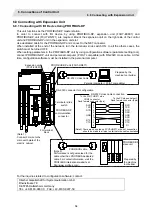
The wirings between operation panel and electric cabinet (or control panel) can be simplified by putting I/O
interfaces around the operation panel together.
Characteristics of operation panel I/O unit are as follows.
(1) Operation panel (display unit section) and electric cabinet (control unit section) can be wired with one
cable (G013).
This is effective to simplify the wiring between operation panel and electric cabinet, as well as to reduce
the cost of wiring.
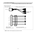
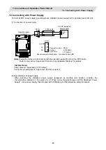
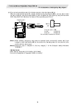
G013 cable includes RI03, EMG and LAN.
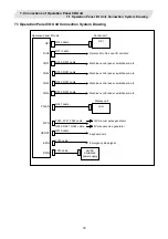
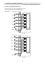
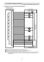
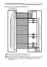
(2) Number of DI/DO points that can be mounted on the machine operation panel is 32/32 as standard and
64/64 at the maximum.
Both sink type and source type are available.
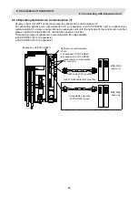
(3) Remote I/O interface --- 1ch
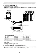
Remote I/O unit, card-sized I/O card, scan I/O card, etc. can be extended up to 5 channels.
Note that the following (a) and (b) will be applied if DI/DO mounted on the operation panel I/O unit is used.
(a) When 32 points/32 points are used, up to 5 channels, or 160 points/160 points in total, are available.
(b) When 64 points/64 points are used, up to 4 channels, or 128 points/128 points in total, are available.
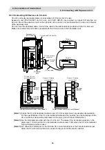
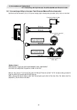
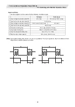
(4) Manual pulse generator --- 3ch
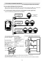
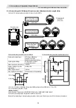
5V and 12V manual pulse generators can be connected.
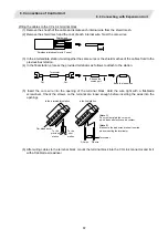
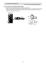
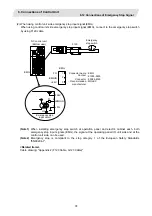
(5) Emergency stop input --- 1ch
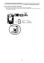
Emergency stop switch installed on the operation panel can be connected.
(6) LAN communication interface --- 1ch
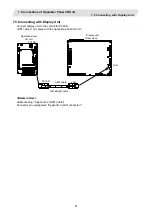
Display unit can be connected.
(7) NC reset interface --- 1ch
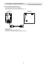
NC can be reset by DI input. NC reset interface is connected to the keyboard unit.
(8) Installation on the back side of the keyboard unit is possible.
Allows space saving inside the operation panel.
(Note)
Operation panel I/O unit is attached to the back side of the keyboard unit when shipped. (This applies
only when purchasing operation panel I/O unit and the keyboard unit together.)

