
MITSUBISHI ELECTRIC VISUAL SOLUTIONS AMERICA, INC.
9351 Jeronimo Road, Irvine, CA 92618-1904
Copyright © 2011 Mitsubishi Electric Visual Solutions America, Inc.
All Rights Reserved
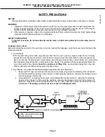
CAUTION:
Before servicing this chassis, it is important that the service person read the "SAFETY PRECAUTIONS" and
"PRODUCT SAFETY NOTICE" contained in this manual.
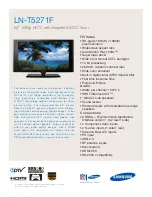
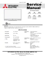
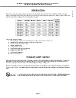
DLP PROJECTION HDTV
SPECIFICATIONS
• Power Input
: AC 120V, 60Hz
• Light Engine
: DLP™ (1080p)
• Light Source
: VIP Lamp
• Antenna Input
: RF 75
unbalanced
• Tuning
: NTSC/ATSC/QAM
:
Analog Cable - 1~125
Digital Cable - 1~135
• Speakers
: 10W x 2 (except V45++)
: 2W x 16 (V45++)
• Analog Input
: Composite/Component
Level
(RCA
Type)
Y/Video: 1.0 Vp-p, Cr, Cb: 700mVp-p
75
unbalanced
: AUDIO IN JACK (RCA Type)
-4.7dBm 43k
unbalanced
• Analog Output : AUDIO / SUBWOOFER OUT JACK
Level
(RCA
Type)
-4.7dBm 4.7k
unbalanced
• Digital
: AC-3/PCM Digital Audio Output
Inputs/Outputs (RCA Type)
:
HDMI™
:
USB
: PC - use HMDI™
:
Wired IR Input/Output (V45++)
: Ethernet (V45CB, V45+, V45++)
: Bluetooth
(V45++)
Manual
Service
• See Page 5 for additional specifications.
• Design specifications are subject to change without notice.
V45C V45 V45CA
WD-73C11 WD-73640 WD-73CA1
V45+ V45++ V45CB
WD-73740 WD-73840 WD-82CB1
WD-82740
WD-82840
WD-92840
Version 3.0 10/13/11
2011
Summary of Contents for DLP WD-82CB1
Page 2: ......