8
Connections
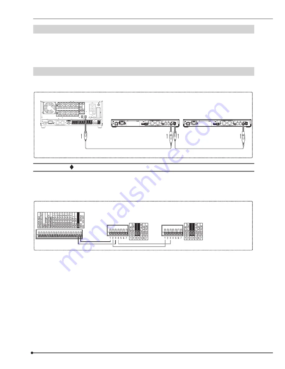
Connectable recorders
MITSUBISHI DIGITAL RECORDER
•
DX-TL5000 series (DX-TL5000U, DX-TL5000E, DX-TL5000UA, DX-TL5000E400, DX-TL5000E(Z))
•
DX-TL4500 series (DX-TL4516E, DX-TL4516E(Z), DX-TL4516U, DX-TL4509E, DX-TL4509E(Z), DX-TL4509U)
The above stated models are connectable as of October 2007. Consult your dealer for the connection with other recorders.
Connection example
•
Connect this unit and a digital recorder by using the supplied USB cable.
•
You can connect multiple DX-ZD6UE as shown below.
Supplied USB cable
Supplied USB cable
To SERIAL BUS port
To SERIAL BUS IN port
To SERIAL BUS
OUT port
To SERIAL BUS
IN port
100-240V
AC IN
~
M
AX
3
50
m
A
DC
1
2V
OUT
CL
OCK
ADJ
CLOCK
A
DJ
OUT
REC REC
ST
OP
EMERG
ENCY
RESER
VED
M
ODE
O
UT
1
+
M
ODE
O
UT
1
–
M
ODE
O
UT
2
+
M
ODE
O
UT
2
–
M
ODE
O
UT
3
+
M
ODE
O
UT
3
–
M
ODE
O
UT
4
+
M
ODE
O
UT
4
–
CAL
L
OUT
+
CAL
L
OUT
–
GND
GND
GND
GND
1
ALARM IN
2 3 4 5 6 7 8 9 10 11 12 13 14 15 16
RS4
85
TERM
+
RS4
85
TERM
–
P T Z
R
S422
+
R
S422
–
R
S232
1
ALARM OUT
2 3 4 5 6 7 8 9 10 11 12 13 14 15 16
RS-232C
RS485
RS485
IN
OUT
MAIN
OFF ON
RESET
OPTION SLOT
LAN-A
LAN-B
STORAGE
COM
SERIAL BUS
SERIAL BUS
1
2
3
4
5
6
7
8
9
10
11
12
13
14
15
16
OUT
IN
CAMERA
OUT
IN
Y/C
OUTPUT B
CLAMPER
CLAMPER
OUTPUT A
VIDEO
VIDEO
VIDEO CASCADE
IN
OUT
10
100
10
100
AUDIO IN
1
2
3
4
OUT
IN
AUDIO
CASCADE
AUDIO OUT
This unit
Digital recorder DX-TL5000E400 (example)
Connection to link the power supply of the recorder and this unit
•
Set the EXTERNAL CONTROL switch to ON (left side) and connect the terminals as shown below. It is recommended
to link this unit with the recorder’s power supply.
•
To resume recording or copying after a power failure during normal recording or timer recording, plug this unit into the
outlet of the same power line that is used for the recorder connected.
Digital recorder DX-TL5000E400 (example)
This unit


