
22
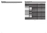
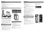
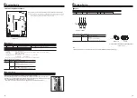
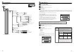
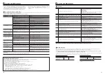
(a) For insertion, push on the SD memory card until it clicks into place.
(b) For ejection, push on the SD memory card until it clicks.
Note:
Logos
Capacities
2 GB to 32 GB *2
SD speed classes
All
5.6 Using SD memory card
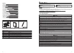
<Handling precautions>
Manufacturer
Model
Tested in
Silicon Power
SP004GBSDH004V10
Jan. 2015
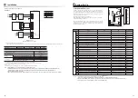
Before using a new SD memory card (including the card that comes with the
unit), always check that the SD memory card can be safely read and written to
by the FTC controller.
<How to check read and write operations>
a) Check for correct wiring of power supply to the system. For more details,
refer to section 4.5.
(Do NOT power on the system at this point.)
b) Insert an SD memory card.
c) Power on the system.
d) The LED4 lamp lights up if the read and write operations are successfully
completed. If the LED4 lamp continues blinking or does not light up, the
SD memory card cannot be read or written to by the FTC controller.
(a)
(b)
7KH6'/RJRLVDWUDGHPDUNRI6'&//&
7KHPLQL6'ORJRLVDWUDGHPDUNRI6'&//&
7KHPLFUR6'ORJRLVDWUDGHPDUNRI6'&//&
*1 To edit main controller settings or to check operating data, an Ecodan
service tool (for use with PC) is required.
$*%6'PHPRU\FDUGVWRUHVXSWRGD\VRIRSHUDWLRQORJV
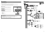
(1) Use an SD memory card that complies with the SD standards. Check that the
SD memory card has a logo on it as those shown on lower right figure.
(2) SD memory cards to the SD standards include SD, SDHC, miniSD, micro SD,
and microSDHC memory cards. The capacities are available up to 32 GB.
Choose that with a maximum allowable temperature of 55ºC.
(3) When the SD memory card is a miniSD, miniSDHC, microSD, or micro SDHC
memory card, use an SD memory card converter adapter.
%HIRUHZULWLQJWRWKH6'PHPRU\FDUGUHOHDVHWKHZULWHSURWHFWVZLWFK
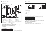
The cylinder unit is equipped with an SD memory card interface in FTC.
Using an SD memory card can simplify main controller settings and can store
operating logs. *1
(5) Before inserting or ejecting an SD memory card, make sure to power OFF the
system. If an SD memory card is inserted or ejected with the system powered
ON, the stored data could be corrupted or the SD memory card be damaged.
*An SD memory card is live for a short duration after the system is powered
off. Before insertion or ejection wait until the LED lamps on the FTC control
board are all off.
(6) The read and write operations have been verified using the following SD
memory cards, however, these operations are not always guaranteed as the
specifications of these SD memory cards could change.
(7) Make sure to follow the instruction and the requirement of the SD memory
card’s manufacturer.
(8) Format the SD memory card if determined unreadable in step (6). This could
make it readable.
Download an SD card formatter from the following site.
SD Association homepage: https://www.sdcard.org/home/
(9) FTC supports FAT file system but not NTFS file system.
(10) Mitsubishi Electric is not liable for any damages, in whole or in part, including
failure of writing to an SD memory card, and corruption and loss of the saved
data, or the like. Back up saved data as necessary.
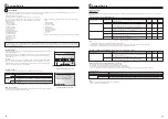
(11) Do not touch any electronic parts on the FTC control board when inserting or
ejecting an SD memory card, or else the control board could fail.
To avoid cutting fingers, do not touch sharp edges of the SD
memory card connector (CN108) on the FTC control board.
CN108
System Set Up
5
Note: Before inserting or ejecting an SD memory card, confirm that the power supply
earth cable is securely connected and prevent the FTC from being applied with
static electricity (e.g. touch a case body etc.). Otherwise, it may cause a failure of
the FTC due to the static electricity.
23
F1
F2
F3
F4
B
C
D
E
A
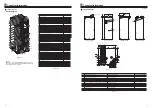
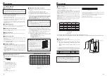
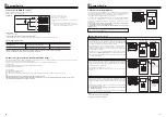
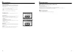
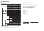
5.7 Main Controller
<Main controller parts>
Letter
Name
Function
A
Screen
Screen in which all information is displayed
B
Menu
Access to system settings for initial set up and
modifications.
C
Back
Return to previous menu.
D
Used to select or save. (Enter key)
E
Power/Holiday
Confirm
If system is switched off pressing once will turn
system on. Pressing again when system is
switched on will enable Holiday Mode. Holding the
button down for 3 secs will turn the system off. (
*1
)
F1-4
Function keys
Used to scroll through menu and adjust settings.
Function is determined by the menu screen visible
on screen A.
*1
When the system is switched off or the power supply is disconnected, the
cylinder unit protection functions (e.g. freeze stat function) will NOT oper-
ate. Please beware that without these safety functions enabled the cylinder
unit and installation may potentially become exposed to damage.
System Set Up
5
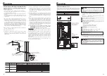
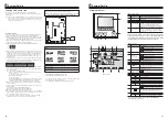
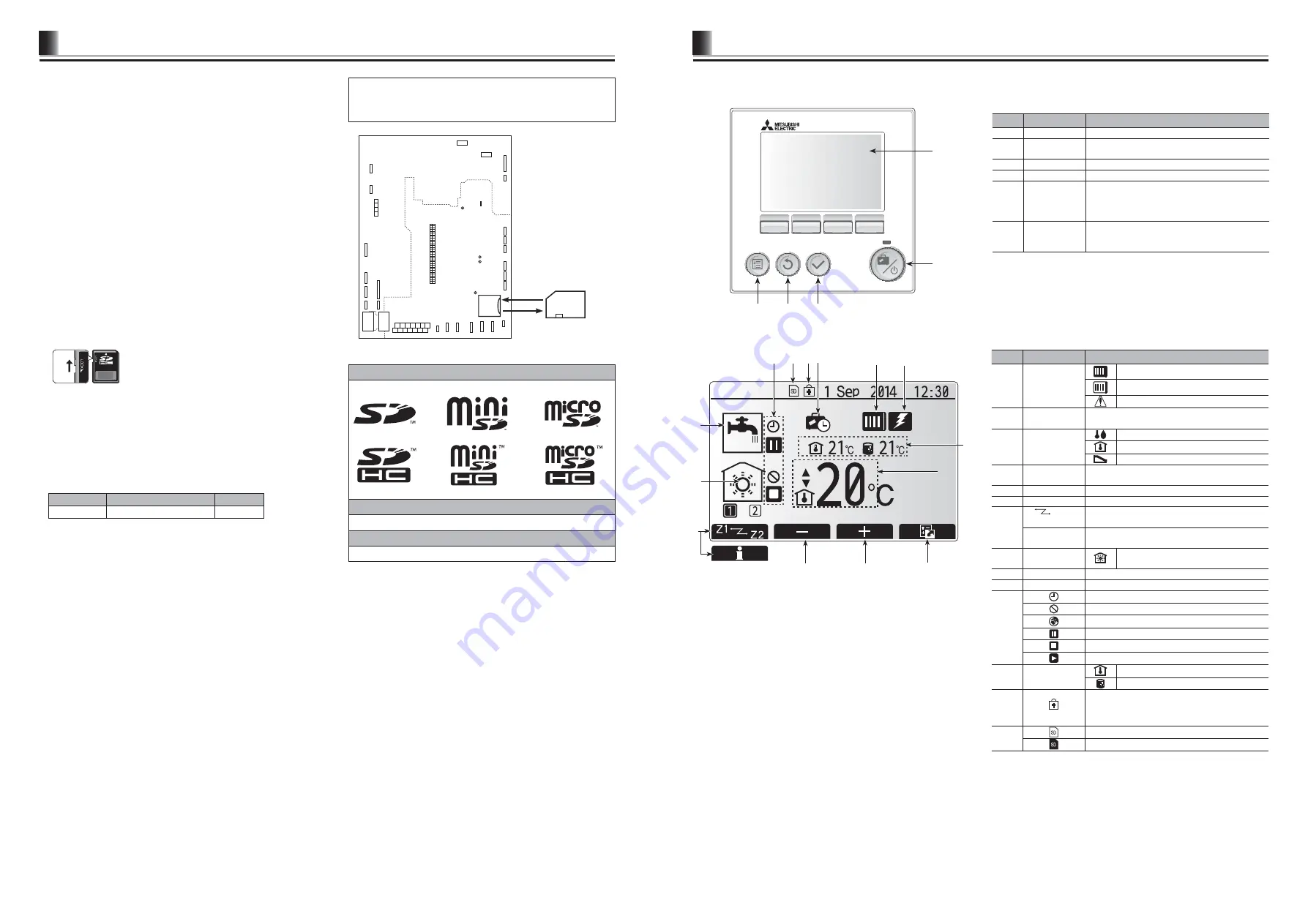
Main screen
<Main screen icons>
Icon
Description
11
10
2
1
9
6
5
4
14 13
12
7
1
Heat pump
‘Heat pump’ is running.
Defrosting.
Emergency heating.
2
Electric heater
When this icon is displayed the ‘Electric heaters’
(booster heater) are in use.
3
Target
temperature
Target room temperature
Target flow temperature
Compensation curve
4
OPTION
Pressing the function button below this icon will dis-
play the option screen.
5
+
Increase desired temperature.
6
-
Decrease desired temperature.
7
Z1
Z2
Pressing the function button below this icon switches
between Zone1 and Zone2.
Information
Pressing the function button below this icon displays
the information screen.
8
Space heating
mode
Heating mode
Zone1 or Zone2
9
DHW mode
Domestic hot water heating mode
10
Holiday mode
When this icon is displayed ‘Holiday mode’ activated.
11
Timer is activated.
Prohibited
Server control is activated.
Stand-by
Stopped
Operating
12
Current
temperature
Current room temperature
Current water temperature of thermal store tank
13
The Menu button is locked or the switching of the
operation modes between DHW and Heating opera-
tions are disabled in the Option screen.(
*2
)
14
SD memory card is inserted. Normal operation.
SD memory card is inserted. Abnormal operation.
*2 To lock or unlock the Menu, press the BACK and CONFIRM keys
simultaneously for 3 seconds.
3
8


