


GCH15010
10
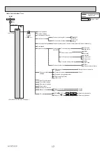
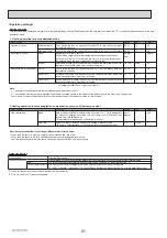
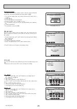
Automatic switch to backup heat source operation
Back-up heat source operation (*1) will automatically run when the outdoor unit stops abnormally. To enable the function, switch DIP SW 2-5 to ON.
To clear the fault(s), reset the power breaker on the indoor unit.
<Applicable error codes (*2)>
E6 to E9, EC, FC, FD, U1 to U4, UP
(*1) Prolonged running of the back-up operation may affect the life of the heat source.
(*2) For safety reasons, this function is not available for certain faults. (System operation must be stopped and only pump keeps running.)
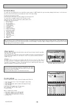
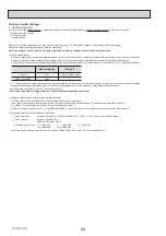
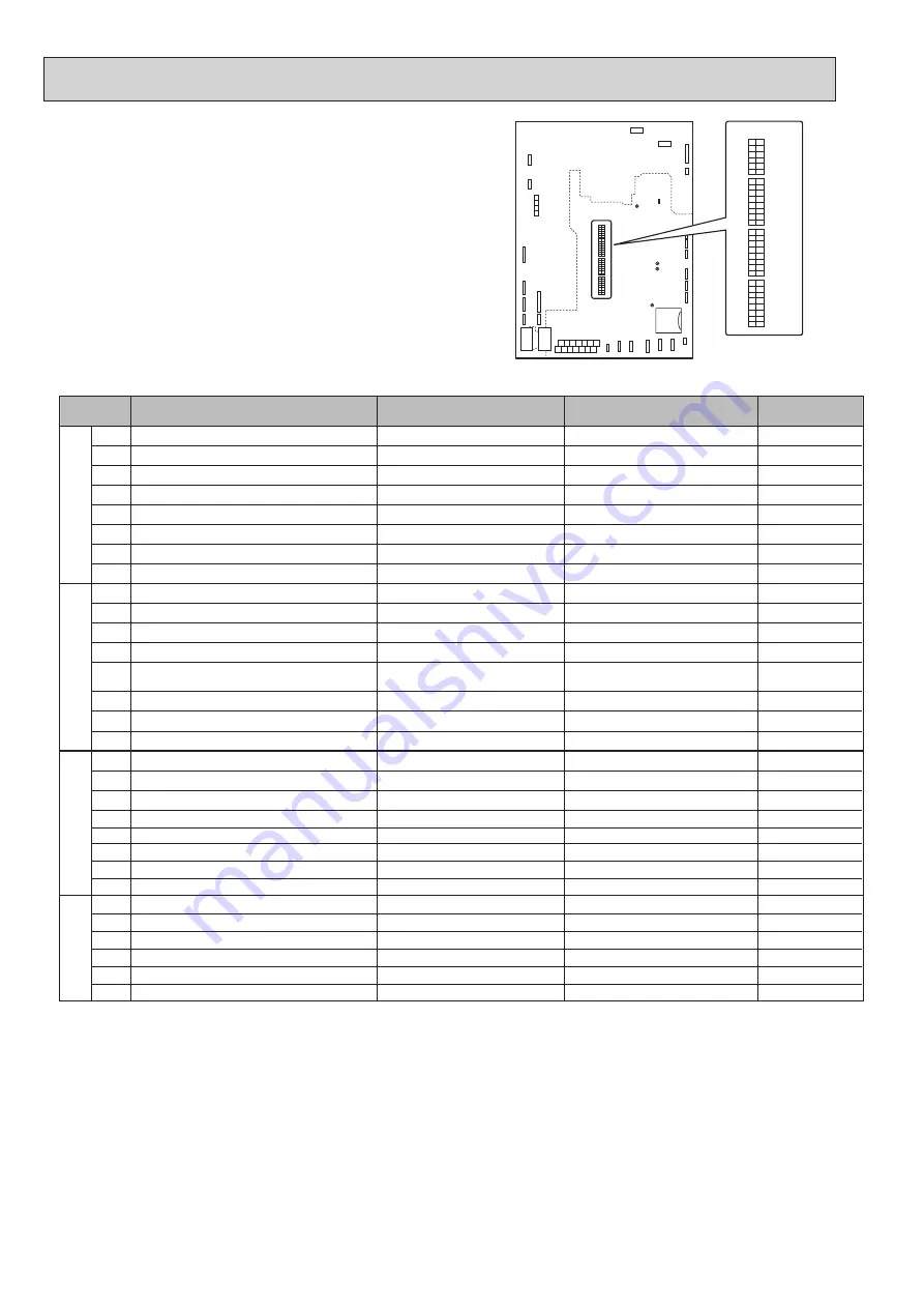
6-2 DIP Switch Functions
Located on the FTC printed circuit board are 4 sets of small white switches
known as DIP switches. The DIP switch number is printed on the circuit board
next to the relevant switches. The word ON is printed on the circuit board and on
the DIP switch block itself. To move the switch you will need to use a pin or the
corner of a thin metal ruler or similar.
DIP switch settings are listed in the table below.
Before changing any switch settings, ensure the power supplies to both cylinder
unit and outdoor unit are turned OFF.
Before changing the DIP switch setting, confirm that the power supply earth
cable is securely connected and prevent the FTC from being applied with static
electricity (e.g. touch a case body etc.). Otherwise, it may cause a failure of the
FTC due to the static electricity.
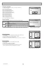
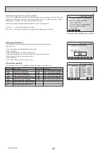
Note: *1.
For safety reasons, this function is not available for certain errors.
(In that
case, system operation MUST be stopped and only the water circulation pump keeps running.)
*2. Space heating and DHW can be operated only in indoor unit, like an electric boiler. (Refer to Installation manual "5.4 Indoor unit only operation". )
*3. If emergency mode is no longer required, return the switch to OFF position.
DIP switch
Function
OFF
ON
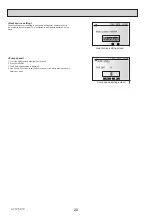
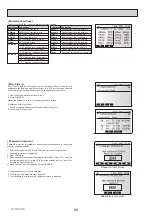
Default settings:
Indoor unit model
SW1 SW1-1
OFF
SW1-2
OFF
SW1-3
OFF
SW1-8 Wireless remote controller
WITHOUT Wireless remote controller WITH Wireless remote controller
OFF
SW2 SW2-1 Room thermostat1 input (IN1) logic change
Zone1 operation stop at thermostat short Zone1 operation stop at thermostat open
OFF
SW2-2
OFF
SW2-4
—
—
—
—
—
—
—
—
—
OFF
SW2-5
Automatic switch to backup heat source operation
(When outdoor unit stops by error)
Inactive
Active *1
OFF
SW2-6
OFF
SW2-7
OFF
SW2-8
OFF
SW3 SW3-1 Room thermostat 2 input (IN6) logic change
Zone2 operation stop at thermostat short Zone2 operation stop at thermostat open
OFF
SW3-2
OFF
SW3-3
OFF
SW3-4 Electric energy meter
WITHOUT Electric energy meter
WITH Electric energy meter
OFF
SW3-5
OFF
SW3-6 2-zone valve ON/OFF control
Inactive
Active
OFF
SW3-7
SW3-8 Heat meter
WITHOUT Heat meter
WITH Heat meter
OFF
SW4 SW4-1
—
—
—
OFF
SW4-2
—
—
—
OFF
SW4-3
—
—
—
—
—
—
OFF
SW4-4 Indoor unit only operation (during installation work) *2
Inactive
Active
OFF
SW4-5 Emergency mode (Heater only operation)
Normal
Emergency mode (Heater only operation) OFF *3
SW4-6
OFF
—
—
—
—
—
—
—
—
—
—
—
—
—
—
—
—
—
—
—
OFF
—
—
—
—
—
—
—
—
SW1-4
OFF
—
—
—
SW1-5
OFF
—
—
—
SW1-6
OFF
—
—
—
SW1-7
OFF
—
—
—
SW2-3
OFF
—
—
—
SW1
SW2
SW3
SW4
OFF ON
1
8
1
8
1
8
1
6


