


GCH15010
23
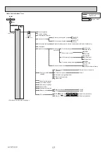
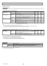
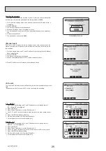
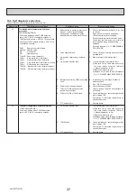
2. Settings using the main remote controller
In this menu, all parameters required to record the consumed electrical energy and the delivered heat
energy which is displayed on the main remote controller can be set. The parameters are an electric
heater capacity, supply power of water pump and heat meter pulse.
Follow the procedure described in General Operation for the set up operation.
For Pump 1, *** can be also set besides this setting.
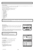
Energy monitor settings menu screen
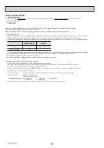
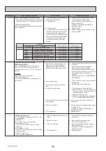
<Running information>
This function shows current temperature and other data of main component parts
of the indoor unit.
1. From the Service menu highlight Running information.
2. Press CONFIRM.
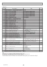
3. Press F3 and F4 buttons to set the Ref. address. *1
4. Use the function buttons to enter index code for the component to be viewed.
(See the Table 9-4-1 for component index codes.)
5. Press CONFIRM.
*1 For multiple outdoor units control system only.
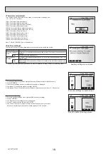
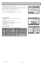
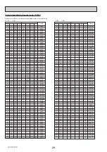
<Thermistor reading>
This function shows the current readings of thermistors located on the water circuit
Thermistor Description
Thermistor Description
TH1A
Zone 1 room temperature
THW6
Zone 1 flow water temperature
TH1B
Zone 2 room temperature
THW7
Zone 1 return water temperature
THW8
Zone 2 flow water temperature
THW1
THW9
Zone 2 return water temperature
THW2
THW3
THW4
THW5A
THW5B
THWB1
Boiler flow water temperature
THWB2
Boiler return water temperature
TH7
Ambient (outdoor) temperature
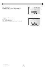
In the case *** is selected, the system acknowledges "factory fitted pump" is selected.
Flow water temp. thermistor
Return water temp. thermistor
Stored water temp. thermistor (lower)
Stored water temp. thermistor (upper)
DHW supply temp. thermistor
Flow water temp. thermistor 2 (to tank)


