GCH15010
42
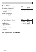
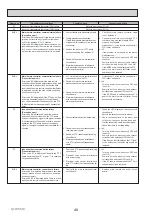
10-5. Troubleshooting by inferior phenomena
No.
Fault symptom
Possible cause
Explanation - Solution
1
Main remote controller
display is blank.
1. There is no power supply to main remote
controller.
1. Check LED2 on FTC. (See 6. WIRING DIAGRAM.)
(i) When LED2 is lit.
Check for damage or contact failure of the main remote controller wiring.
(ii) When LED2 is blinking.
Refer to No. 5 below.
(iii) When LED2 is not lit.
Refer to No. 4 below.
2. Power is supplied to main remote
controller, however, the display on the
main remote controller does not appear.
2. Check the following:
Disconnection between the main remote controller cable and the FTC control
board
)DLOXUHRIWKHPDLQUHPRWHFRQWUROOHULI³3OHDVH
Wait” is not displayed.
5HIHUWR1REHORZLI³3OHDVH
Wait” is displayed.
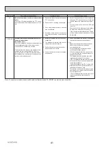
2
³
Please Wait” remains
displayed on the main
remote controller.
1. "Please Wait" is displayed for up to 6
minutes.
1. Normal operation
2. Communication failure between the main
remote controller and FTC.
2, 3. Main remote controller start up checks/procedure.
(i)
,I³´RU³´LVGLVSOD\HGEHORZ3OHDVH
Wait" there is a
communication error between the main remote controller and the FTC control
board.
&KHFNZLULQJFRQQHFWLRQVRQWKHPDLQUHPRWHFRQWUROOH
r.
5HSODFHWKHPDLQUHPRWHFRQWUROOHURUWKH)7&FRQWUROERDUG
(ii) If
³´
is displayed there is a communication error between the outdoor
unit's and FTC's control boards.
Check the wiring connections on the outdoor unit control board and the FTC
control board.
(Ensure S3 is securely wired with no damage. (See 7. FIELD WIRING.)
5HSODFHWKHRXWGRRUXQLWVDQGRUWKH)7&VFRQWUROERDUGV
3. Communication failure between FTC and
outdoor unit.
3
The main screen
appears with a press
RIWKH³21´EXWWRQEXW
disappears in a second.
The main remote controller operations do
not work for a while after the settings are
changed in the service menu. This is because
the system takes time to apply the changes.
Normal operation
The cylinder unit is applying updated settings made in the service menu.
Normal operation will start shortly.
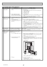
4
LED2 on FTC is off.
(See 6. WIRING
DIAGRAM.)
When LED1 on FTC is also off. (See 6.
WIRING DIAGRAM.)
1.
)7&LVQRWVXSSOLHGZLWKWR9
AC.
1. Check the voltage across the L and N terminals on the indoor power supply
terminal block 1. (See 7. FIELD WIRING.)
:KHQWKHYROWDJHLVQRWWR9
AC, check for faulty wiring to power
supply.
:KHQWKHYROWDJHLVWR9
AC, go to 2. below.
2. There are problems in the method of
connecting the connectors.
2.
Check for faulty wiring between the connectors.
When the connectors are wired incorrectly
UHZLUH
them correctly referring
to below. (See 7. FIELD WIRING and a wiring diagram on the control and
electrical box cover.)
If there is no problem with the wiring, go to 3. below.
3. FTC failure.
3. Check the FTC control board.
&KHFNWKHIXVHRQ)7&FRQWUROERDUG
&KHFNIRUIDXOW\ZLULQJ
If there is no problem with the wiring, the FTC control board is faulty
.
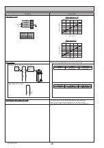
Modified settings
(Separate power supply to the cylinder unit)
L
N
Cylinder unit
Cylinder unit
control board
&128&
White
Black
XBL
TB1
TB2
28&
XBN
&1
CN3C
S1 S2 S3
2XWGRRUXQLW
S1
S2
S3

