


GCH15010
5
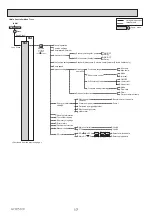
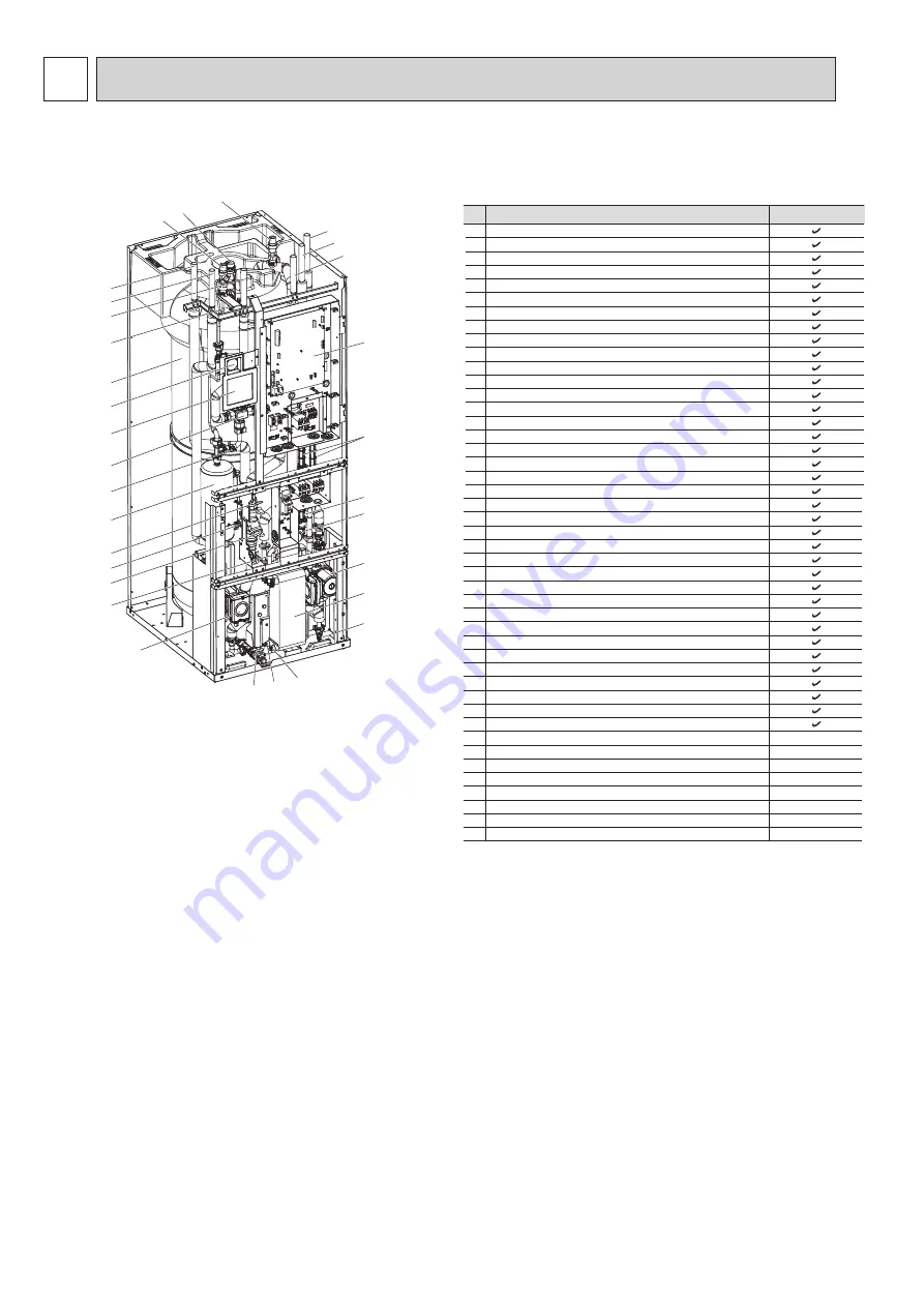
PART NAMES AND FUNCTIONS
4
No.
Part name
A
DHW outlet pipe
B
Cold water inlet pipe
C
Water pipe (Space heating return connection)
E
Water pipe (Flow from heat pump connection)
F
Water pipe (Return to heat pump connection)
3
Booster heater with thermostat
4
3-way valve
5
Manual thermostat
6
Manual air vent (above tank)
7
Manual air vent (above pump A)
8
Drain valve (Primary circuit)
9
Manometer
10
Primary pressure relief valve (3bar)
11 Automatic air vent
12 Flow sensor 1 (For space heating)
13 Flow sensor A (Secondary (Potable) circuit)
14 Flow sensor B (Primary circuit)
15 Strainer valve
16 Water circulation pump A (For hot water supply to plate heat exchanger)
17 Pump valve
18 Primary thermal store tank
19 Plate heat exchanger (Water - Water)
20 Water circulation pump 1 (For thermal store and space heating)
1
Control and electrical box
2
Main controller
Water pipe (Space heating flow connection)
D
EHPT20Q-VM2EA
21 THW1 (Flow water temp. thermistor)
22 THW2 (Return water temp. thermistor)
23 Drain cock (HEX) (Secondary (Potable) circuit)
26 Drain cock (For pump A)
27
28 THW5B (Stored water temp. thermistor (lower))
29 THW3 (Flow water temp. thermistor 2 (to tank))
Drain cock (Booster heater)
THW5A (Stored water temp. thermistor (upper))
25
30 THW4 (DHW supply temp. thermistor)
31 Electrical isolation pipe
32 Primary expansion vessel (Accessory item)
33 Drain pipe (Local supply)
34
35
Tundish (Accessory item)
Isolating valve (Local supply)
36 Magnetic filter (Local supply) (Recommended)
37 Strainer (Local supply)
38 Filling loop (Ball valves, check valves and flexible hose) (Accessory item)
Thermo mix valve (recommended) (Local supply)
39
—
—
—
—
—
—
—
—
Drain cock (HEX) (Primary circuit)
24
EHPT20Q-VM2EA
<Note>
Ű
Component Parts
6
F
D
E
B
A
10
11
9
18
2
4
5
3
15
14
12
25
20
C
1
13
7
16
26
8
19
31
23
24
10
Make sure to correctly install the Mitsubishi Electric Accessory
Parts (e.g. Primary expansion vessel, Tundish and Filling loop)
in the field.


