GCH15010
53
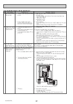
DISASSEMBLY PROCEDURE
PHOTOS
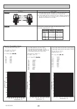
Photo 5-1
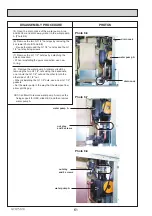
Photo 5-2
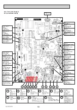
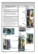
Photo 5-3
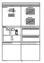
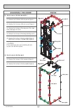
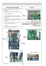
Figure 2-1
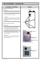
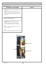
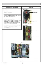
< CAUTION >
The thermistor is located
inside insulation.
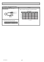
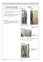
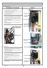
5. How to remove the thermistor
5-1. How to remove the thermistor THW1,THW2
Thermistor - THW5A,THW5B
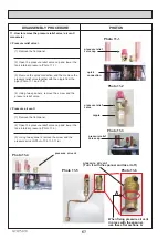
There are three kinds thermistor in total as follows.
Each connector of thermistors is correspond to
①〜③
in Photo 5-1.
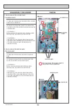
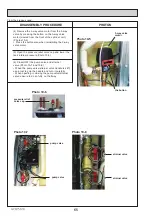
Thermistor - THW1,THW2
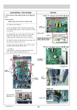
The state the thermistor
THW2 is removed.
Thermistor THW2
The state the thermistor
THW1 is removed.
Thermistor THW1
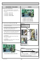
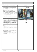
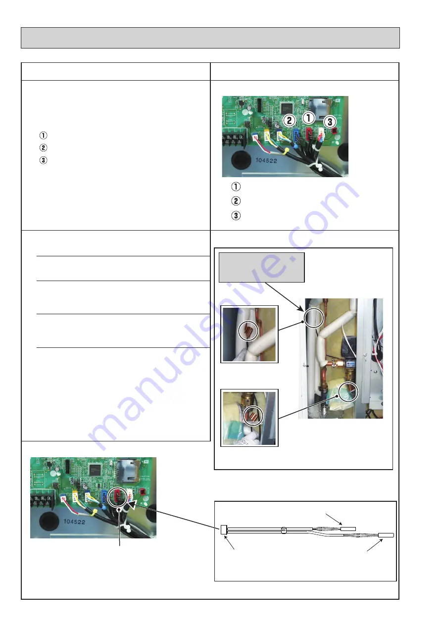
Connector (RED) of thermistor THW1,THW2
Connector (RED)
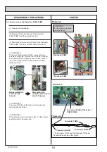
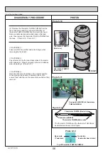
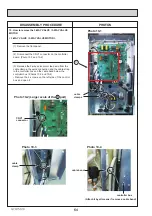
Thermistor - THW3,THW4
CNW12 connector (RED)
CNW3 connector (BLUE)
CNW5 connector (WHITE)
(1) Remove the front panel.
The thermistor THW1 and the thermistor THW2 are
assembled as shown in this Figure.
(2) Remove the copper clamps of the thermistor
THW
1,THW2 from the pipes.(Photo 5-2
)
(3) Disconnect the connector (RED) of the thermistor
THW
1,THW2 from the controller board.(Photo 5-3
)
< CAUTION(1) >
Take care NOT to pull the lead wire strongly when
removing the thermistor.
< CAUTION(2) >
When placing a new thermistor, place it in the original
position where it was removed.


