
GCH15010
54
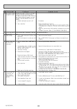
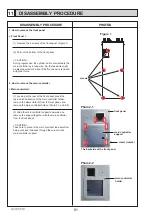
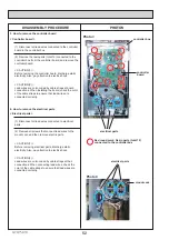
DISASSEMBLY PROCEDURE
PHOTOS
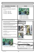
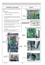
Photo 5-4
Photo 5-5
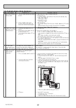
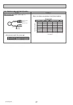
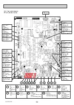
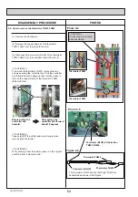
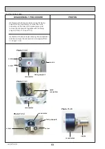
Figure 2-2
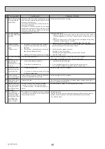
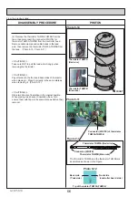
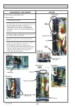
< CAUTION >
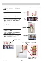
The thermistor is located
inside insulation.
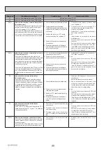
5-2. How to remove the thermistor THW3,THW4
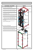
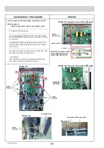
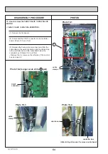
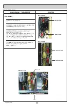
(1) Remove the front panel.
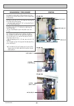
Before pulling the
controller box
forward
After pulling the
controller box forward
about 30 degrees
(2) Remove the copper clamps of the thermistor
THW
3,THW4 from the pipes.(Photo 5-4
)
(3) Disconnect the connector (BLUE) of the thermistor
THW
3,THW4 from the controller board.(Photo 5-5
)
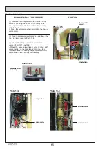
< CAUTION(1) >
To remove the thermistor THW3, remove the two
screws securing the controller box. Pull the controller
box forward about 30 degrees, then it makes easy to
remove the copper clamp of the thermistor THW3 .
(Below photos)
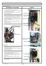
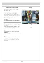
< CAUTION(2) >
Take care NOT to pull the lead wire strongly when
removing the thermistor.
< CAUTION(3) >
When placing a new thermistor, place it in the original
position where it was removed.
Screws
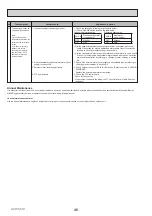
Thermistor THW3
Thermistor THW4
Connector (BLUE) of thermistor
THW3,THW4
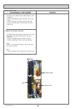
Thermistor THW3
Thermistor THW4
Connector (BLUE)
The thermistor THW3 and the thermistor THW4 are
assembled as shown in this Figure.


