GCH15010
56
DISASSEMBLY PROCEDURE
PHOTOS
Figure 2-3
Photo 5-10
Photo 5-11
Photo 5-12
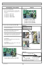
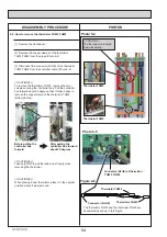
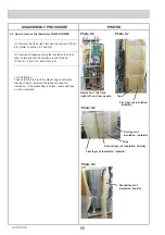
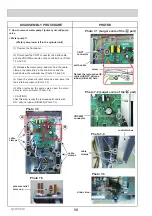
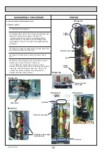
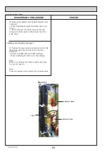
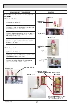
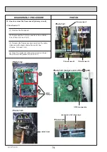
(3) Remove the thermistor THW5A,THW5B from the
tank, then disconnect the connector (WHITE) for
thermistor THW5A,THW5B from the controller boad.
Remove cable clamps and cable bands in the lead
wire, then remove the thermistor THW5A,THW5B from
the tank.
(
Photo 5-10, Photo 5-11
)
< CAUTION(2) >
Take care NOT to pull the lead wire strongly when
removing the thermistor.
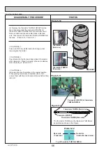
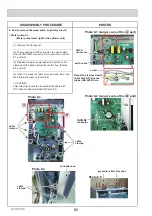
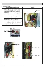
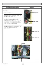
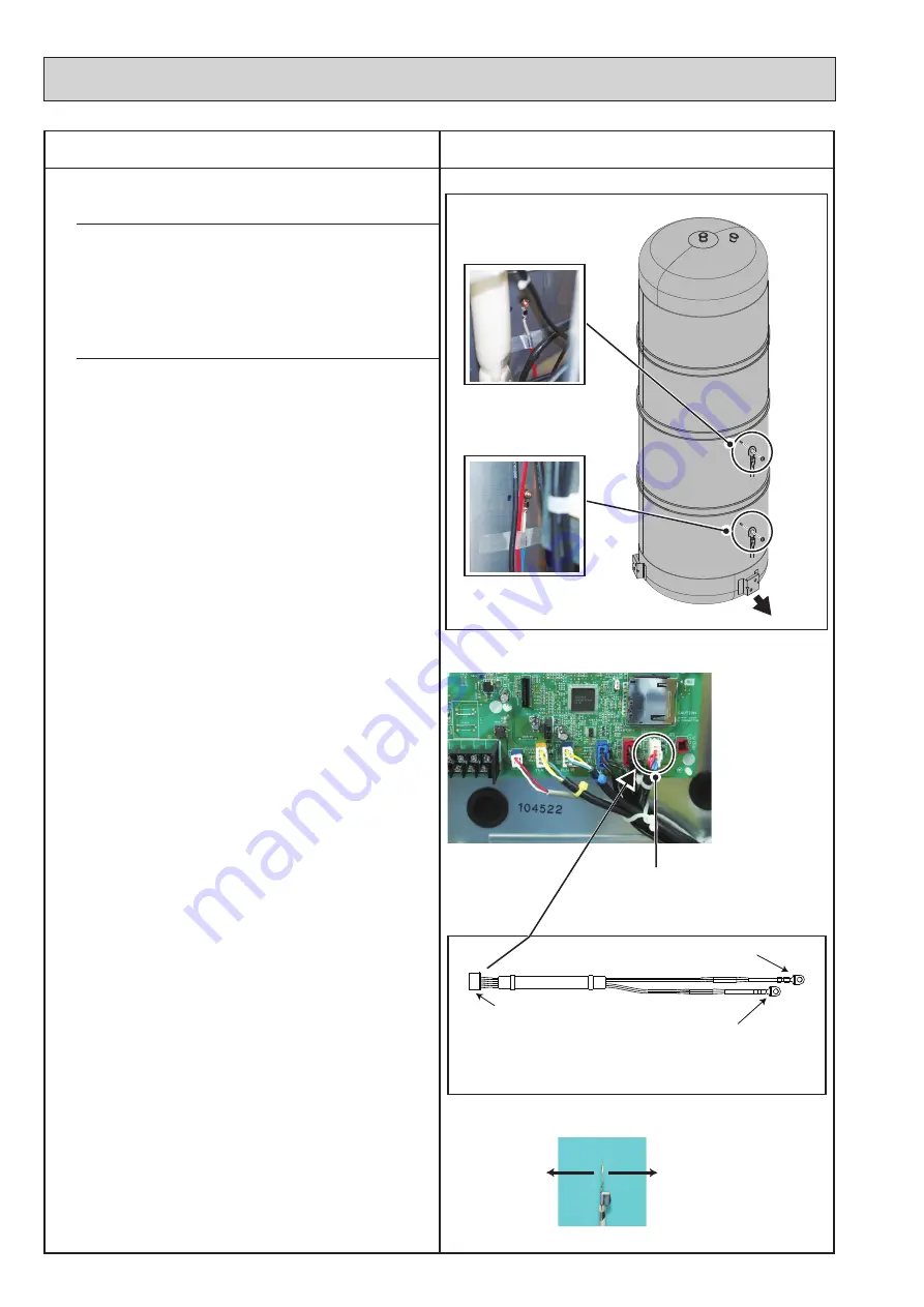
< CAUTION(3) >
Pay attention to the front and back sides of thermistor
when placing it. Place it correctly in the same state as
when removing it. (Photo 5-12)
< CAUTION(4) >
Place two sheets of insulation in the original position.
When placing two sheets of insulation, be sure to
secure them with tape in the same state as before their
removal.
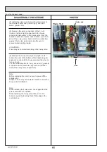
From the previous page.
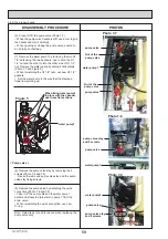
Thermistor THW5A
(Red wire)
Thermistor THW5A (Red wire)
Thermistor THW5B
(Blue wire)
Thermistor THW5B (Blue wire)
FRONT
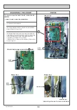
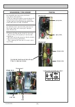
Connector (WHITE) of thermistor
THW5A,THW5B
Back side
(Tank side)
Front side
(controller board side )
Tip of thermistor THW5A,THW5B
Connector (WHITE)
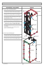
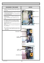
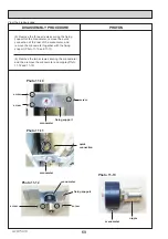
The thermistor THW5A and the thermistor THW5B are
assembled as shown in this Figure.


