


GCH15010
6
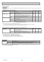
OUTLINES AND DIMENSIONS
5
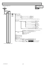
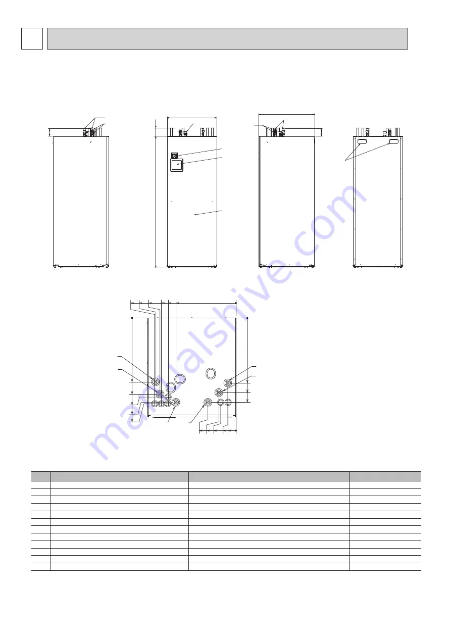
5-1. Technical Drawings
<Unit: mm>
<Top>
< Table 5.1 >
438.1
503.1
568.1
430.6
513.1
533.1
568.1
578.1
55
52.5
102.5
115
405.8
457.5
502.5
512.5
542.5
547.5
0
189.2
0
0
0
B
A
F
E
C
D
① ② ③
④
⑤ ⑥
Letter Pipe and cable description
Connection size/type
A
DHW outlet connection
22 mm/Compression
B
Cold water inlet connection
22 mm/Compression
C
Space heating return connection
22 mm/Compression
D
22 mm/Compression
E
Flow from heat pump connection (No plate heat exchanger) 22 mm/Compression
F
Return to heat pump connection (No plate heat exchanger)
22 mm/Compression
Space heating flow connection
①
Booster heater inlet (Power cable 230 V)
Run booster heater cable
②
Main power inlet (Power cable 230 V)
Run power cable
③
Cylinder unit - outdoor unit cable (Power cable 230V)
Run cylinder unit -outdoor unit cable
④
Run output cable
⑤
Signal input cable inlet
Run signal input cables and remote sensor wires
⑥
Wireless receiver and Wi-Fi interface cable inlet
Run wireless receiver cable and ecodan Wi-Fi interface (option) cable
Output cable inlet
—
—
65 m
65 m
15 m
15 m
—
—
15 m
—
—
—
Pipe or cable length (Max.)
<Left side>
<Back side>
<Front>
<Right side>
Air vent
Manometer
Main controller
Front panel
Presser relief valve
Rc1/2
Presser relief
valve
Rc1/2
Handle
680
595
1600
100
90
93


