GCH15010
70
PHOTOS
DISASSEMBLY PROCEDURE
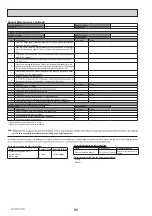
Photo 12-2
Photo 12-4
A
B
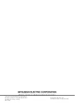
Photo 12-3 (Larger scale of the A part)
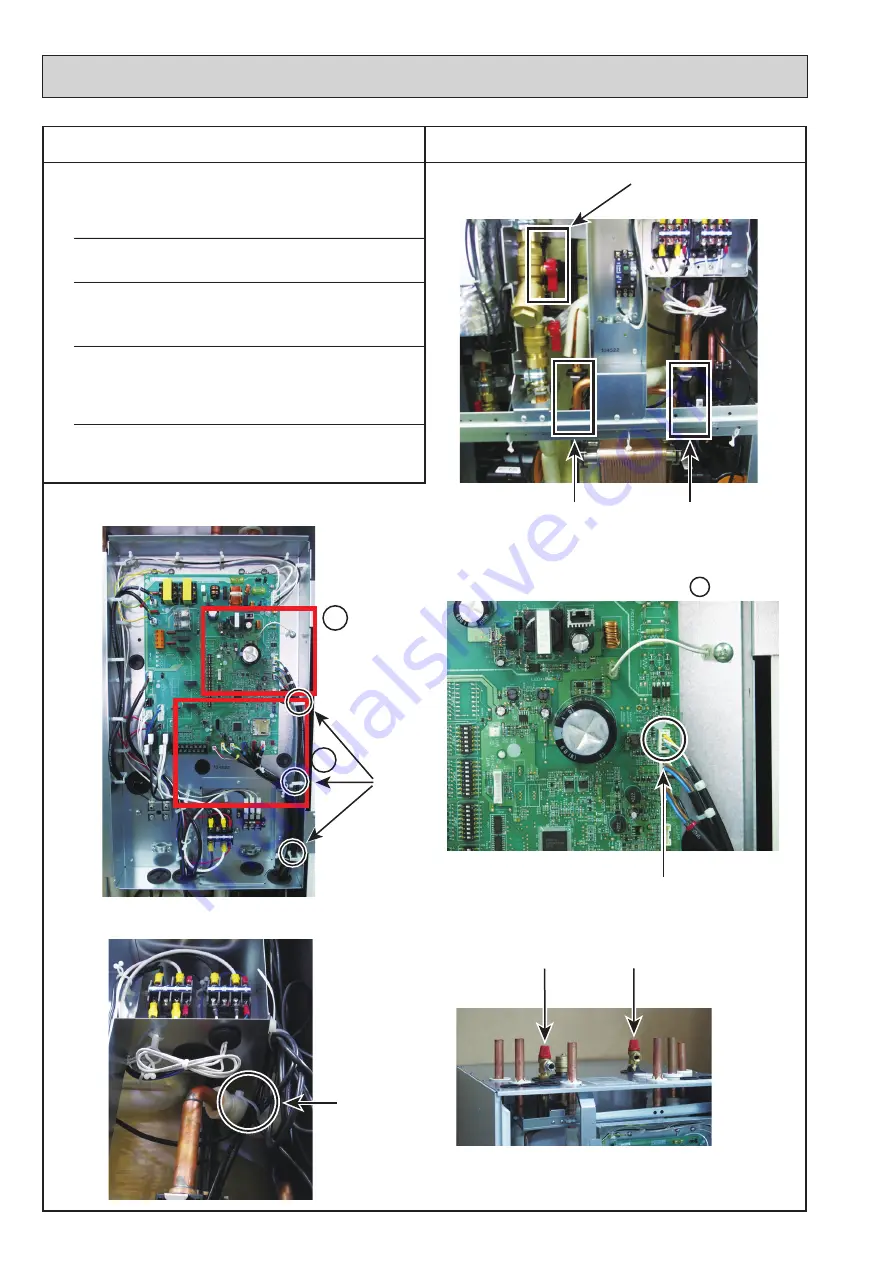
Photo 12-5
Photo 12-1
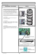
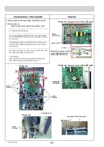
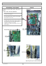
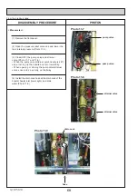
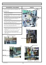
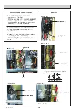
12. How to remove the flow sensor1(primary circuit)
< Flow Sensor 1 >
(1) Remove the front panel.
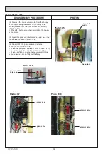
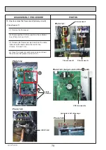
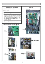
(2) Disconnect the CN1A connector in the controller
box. (Photo 12-2 and 12-3)
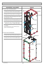
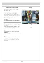
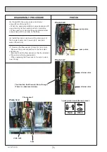
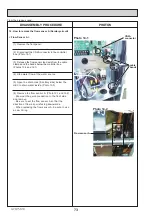
(3) Release the flow sensor lead wire from the cable
clamps and the bands below the control box.
(Photos 12-2 and 12-4)
cable
clamps
CN1A connector
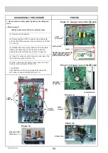
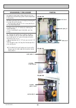
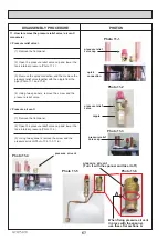
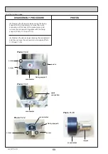
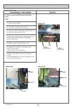
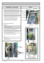
(4) Open the pressure relief valve caps and lower
the tank internal pressure.(Photo 12-5)
pressure relief valve caps
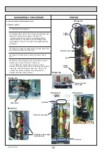
cable band
Flow sensor 1
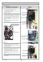
Flow sensor B
Flow sensor A


