
GCH15010
72
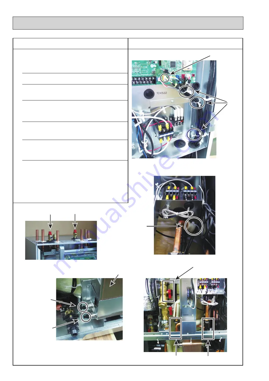
PHOTOS
DISASSEMBLY PROCEDURE
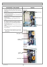
Photo 13-1
Photo 13-2
Photo 13-4
Photo 13-5
Photo 13-3
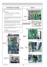
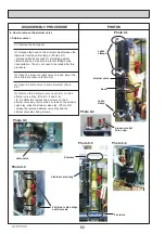
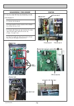
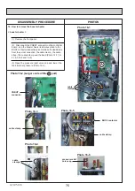
13. How to remove the flow sensor B (primary circuit)
< Flow Sensor B >
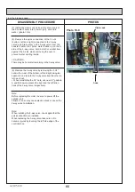
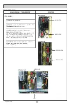
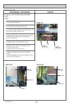
(1) Remove the front panel.
(2) Disconnect the CN2B connector in the controller
box. (Photo 13-1)
(3) Release the flow sensor lead wire from the cable
clamps and the bands below the controller box.
(Photos 13-1 and 13-2)
CN2B
connector
cable
bands
cable band
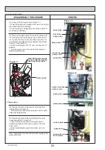
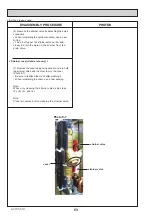
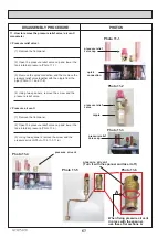
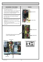
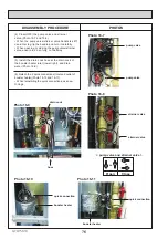
drain cock
(the primary side)
hex
drain cock
(the sanitary side)
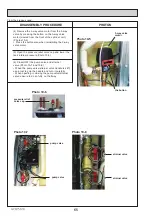
(4) Open the pressure relief valve caps and lower
the tank internal pressure.(Photo 13-3)
(5) Open the drain cock (Primary side) below the
HEX to drain water inside.(Photo 13-4)
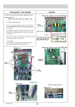
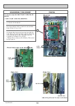
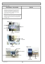
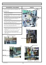
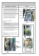
(6) Remove the flow sensor B. (Photo 13-5)
・
Draw out the quick connection to the front side
and remove.
・
Be sure to set the flow sensor B so that the
direction of flow arrow is facing downwards.
・
When replacing the flow sensor B, be sure to use
a new O-ring.
Flow sensor 1
Flow sensor B
Flow sensor A
pressure relief valve caps


