


GCH15010
8
6
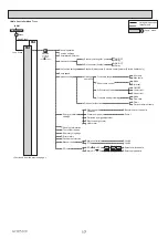
WIRING DIAGRAM
TBI.1
13
10
12
14
11
7
4
6
5
9
3
2
8
1
1
2
CN20 (RED)
TH1
t
°
1
5
THW5A
CNW5 (WHT)
t
°
1
3
5
7
1
5
X6
F1
F2
MP1
M
1~
1
3
CNV1
(WHT)
1
4
CNBHT
(BLK)
CNOUC
(BLU)
CNBC
(GRY)
CNBH
(WHT)
X4
XA
X3
X1
1
1
3
3
3
CNP1
(WHT)
CNPA
(RED)
CNPWM
(WHT)
TAB1
MPA
M
1~
1
3
CNOUT
(WHT)
2
4
1
3
1
2
4
6
CN01
(WHT)
3
4
TBO.1
2WV2a
X13
IN6
IN1
IN8
IN9
IN10
Main
controller
1
2
CN22
(BLU)
CNW12 (RED)
THW5B
t°
1
5
THW1
t
°
THW2
t
°
CNW3 (BLU)
1
5
THW3
t
°
THW4
t
°
2WV2b
M
1~
1
2
TBO.1
1
3
CNPWM3
(RED)
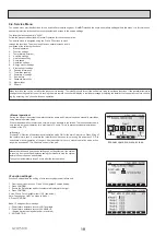
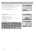
Outline view
Top view
<How to use TBO.1>
Connect them using either way as shown below.
3WV
M
1~
M
1~
Symbol
Name
TB1
Terminal block <Power supply>
ECB
Earth leakage circuit breaker for booster heater
MP1
Water circulation pump 1
(Thermal store & space heating)
MPA
Water circulation pump A (Hot water supply)
3WV
3-way valve
2WV2a 2-way valve (For Zone 1)(Local supply)
2WV2b 2-way valve (For Zone 2)(Local supply)
OUC
Contactor for outdoor unit
OUT
Thermostat for outdoor unit
BHC2
Contactor for booster heater protection
BHC1
Contactor for booster heater
BH1
Booster heater 1
BHF
Thermal fuse for booster heater
BHT
Thermostat for booster heater
TB2
Terminal block <Outdoor unit>
Power supply
~/N 230V 50Hz
CIRCUIT
BREAKER
WHT
WHT
BLK
WHT
BLK
BLK
WHT
WHT
1
2
CN3C
(YLW)
WHT
WHT
WHT
BLK
WHT
CN01
(WHT)
2
1
4
6
S3
S2
S1
To outdoor unit
TB2
TB1
1
3
CNOUC
(BLU)
2
4
CNOUT
(WHT)
OUT
N
L
XBN
OUC
XBL
2
1
4
CNBHT
(BLK)
2
L
(1)
N
(3)
WHT/No.1
WHT/No.2
WHT
BLK
BHC2
6
2
5
1
A1
A2
2 4
Power supply
to Booster heater
~/N 230V 50Hz
ECB
1
3
CNBC
(GRY)
2
1
3
CNBH
(WHT)
2
BHF
BH1
BHT
BLU
BLK
BLK
BLU
WHT
WHT
WHT
BLK
BHC1
6
2
5
1
A1
A2
RED
RED
LED1
CN01
(WHT)
CN3C
(YLW)
CN20
(RED)
CN22
(BLU)
1
5
CNIT
(BLU)
1
5
CN105
(RED)
1
5
CNRF
(WHT)
CNW5
(WHT)
CNW12
(RED)
CNW3
(BLU)
CN2B
(YLW)
CN2A
(BLU)
1
3
CNPWM3
(RED)
1
3
CNPWM
(WHT)
1
4
CN1A
(WHT)
1
2
4
6
1
2
1
5
1
5
1
4
1
4
1
2
1
2
TBI.1
XBL
12 14
6
10
8
13
7
11
9
4
5
3
2
1
SW1
SW2
SW3
SW4
1
8
1
8
1
8
1
6
F1
10A 250V
F2
6.3A 250V
CN108
SD memory
card
CNP1
(WHT)
1
3
CNPA
(RED)
1
3
CNV1
(WHT)
1
5
TBO.1
1
2
3
4
CNOUC
(BLU)
CNBC
(GRY)
CNBH
(WHT)
1
3
CNOUT
(WHT)
2
4
CNBHT
(BLK)
1
4
1
3
1
7
LED4
TAB1
LED2
LED3
Wireless receiver
(Option)
WiFi adapter
(Option)
1
5
1.Symbols used in wiring diagram are,
:connector, : terminal block.
2.Indoor unit and outdoor unit connecting
wires have polarities, make sure to match
terminal numbers (S1, S2, S3) for correct
wirings,
3.Since the outdoor unit side electric wiring
may change, be sure to check the outdoor
unit electric wiring diagram for service.
Symbol
Name
TH1
Thermistor (Room temp.)(Option)
IN1
Room thermostat 1 (Local supply)
THW1
Thermistor (Flow water temp.)
THW2
Thermistor (Return water temp.)
THW3
Thermistor (Flow water (to tank) temp.)
THW4
Thermistor (DHW supply temp.)
THW5A Thermistor (Stored water (upper) temp.)
THW5B Thermistor (Stored water (lower) temp.)
IN6
Room thermostat 2 (Local supply)
IN8
Electric energy meter 1 (Local supply)
IN9
Electric energy meter 2 (Local supply)
IN10
Heat meter (Local supply)
INDOOR CONTROLLER (FTC)
TBO.1
Terminal block <Outputs>
TBI.1
Terminal block <Signal Inputs>
F1
Fuse (T10AL250V)
F2
Fuse (T6.3AL250V)
SW1-4
DIP switch *See Table 3
X1-13
Relay
LED2
Power supply (Main controller)
LED3
Communication (Outdoor unit)
LED4
Reading or writing data to SD card
CNPWM
Pump speed control signal for MP1
CNPWM3
Pump speed control signal for MPA
CN108
SD card connector
XBL
Relay for outdoor unit
XBN
Relay for outdoor unit
LED1
Power supply
6
2
5
1
A1
A2
Flow sensor 1 For space heating
Flow sensor A Potable side
Flow sensor B Primary side
1
4
CN1A
(WHT)
Flow sensor 1
1
4
CN2A
(BLU)
Flow sensor A
1
4
CN2B
(YLW)
Flow sensor B
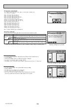
XBN
Tool
Tool
Conductor
Conductor
6-1-1 Cylinder unit WIRING DIAGRAM <EHPT20Q-VM2EA>
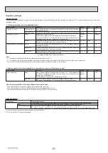
Table 1 Signal Inputs
Name Terminal block Connector
Item
OFF (Open)
ON (Short)
IN8 TBI.1 5-6
—
Electric energy meter 1
IN9 TBI.1 7-8
—
Electric energy meter 2
IN10 TBI.1 9-10
—
Heat meter
Refer to installation manual.
IN1 TBI.1 3-4
—
Room thermostat 1 input
Refer to SW2-1 in<Table 3 DIP Switch Functions>.
IN6 TBI.1 1-2
—
Refer to SW3-1 in<Table 3 DIP Switch Functions>.
Room thermostat 2 input
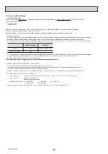
Table 2 Outputs
Name Terminal block
Connector
Item
OFF
ON
OUT1
ー
CNP1
Water circulation pump1 output (Space heating & DHW)
OFF
ON
OUTA
ー
CNPA
Water circulation pump A output
OFF
ON
OUTB
ー
—
Relay for outdoor unit
OFF
ON
OUT4
ー
CNV1
3-way valve output
Heating
DHW
OUT6
ー
CNBH 1-3 Booster heater output
OFF
ON
OUT3 TBO.1 1-2
—
2-way valve 2b output *1
OFF
ON
*1. For 2-zone valve ON/OFF control.
Do not connect to the terminals that are indicated as “
ー
“ in the “Terminal block” field.
OUT13 TBO.1 3-4
—
2-way valve 2a output *1
OFF
ON


