12
S1
S2
S3
L
N
L
N
BLACK
BLACK
YELLOW
YELLOW
YELLOW
YELLOW
BLACK
BLACK
CNO1
CNO1
CNO1
Black
CNO1
Black
FTC4
(Master)
FTC4
(Master)
S1
S2
S3
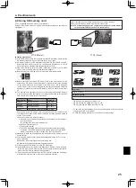
Initial settings
(Power supplied
by outdoor unit)
Modified settings
(Separate power
supply to
FTC4(Master))
Power
supply
~/N
230V
50Hz
Earth
leakage
breaker
Wiring
circuit
breaker
or
Isolating
switch
L
N
S1
S2
S3
Outdoor unit
S1
S2
S3
TB2
TB1
L
N
ECB
Wiring
circuit
breaker
or
Isolating
switch
To control
board
ELB for
immersion
heater
(DHW tank)
L
N
Power
supply
~/N
230V
50Hz
Earth
leakage
breaker
Wiring
circuit
breaker
or
Isolating
switch
Power
supply
circuit
circuit
: PAC-IF051B-E
: PAC-IF052B-E
FTC4 (Master)
Power
supply
3N~
400V
50Hz
Earth
leakage
breaker
Wiring
circuit
breaker
or
Isolating
switch
L3
L2
L1
N
S1
S2
S3
Outdoor unit
S1
S2
S3
TB2
TB1
L
N
ECB
Wiring
circuit
breaker
or
Isolating
switch
To control
board
ELB for
immersion
heater
(DHW tank)
L
N
Power
supply
~/N
230V
50Hz
Earth
leakage
breaker
Wiring
circuit
breaker
or
Isolating
switch
Power
supply
circuit
circuit
FTC4 (Master)
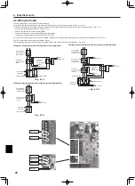
4. Electrical work
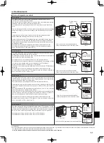
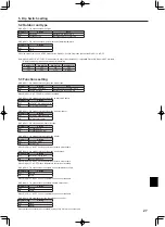
Option 2: FTC4 (Master) powered by independent source
If FTC4 (Master) and outdoor units have separate power supplies, the following require-
ments MUST be carried out:
• FTC4 (Master) unit electrical box connector connections changed (see Fig. 4.1.3)
• Outdoor unit DIP switch settings changed to SW-3 ON
• Turn on the outdoor unit before the FTC4 (Master).
<Fig. 4.1.3>
<Fig. 4.1.5>
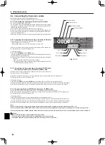
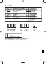
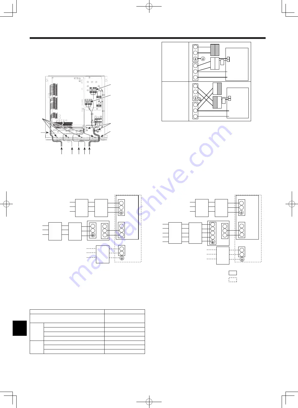
Electrical connections 1 phase/3 phase
FTC4 (Master) power supply
~/N 230 V 50 Hz
FTC4 (Master) input capacity
Main switch (Breaker)
*1
16 A
Wiring
Wiring No.
× size (mm²)
FTC4 (Master) power supply
2 × Min. 1.5
FTC4 (Master) power supply earth
1 × Min. 1.5
FTC4 (Master) - Outdoor unit
*2
2 × Min. 0.3
FTC4 (Master) - Outdoor unit earth
—
Circuit
rating
FTC4 (Master) L - N
*3
AC230V
FTC4 (Master) - Outdoor unit S1 - S2 *3
—
FTC4 (Master) - Outdoor unit S2 - S3 *3
DC24V
Note: In accordance with IEE regulations the circuit breaker/isolating switch located on the outdoor unit should be installed with lockable devices (health and safety).
*1. A breaker with at least 3.0 mm contact separation in each pole shall be
provided. Use earth leakage breaker (NV).
The breaker shall be provided to ensure disconnection of all active phase
conductors of the supply.
*2. Max. 120 m
*3. The values given in the table above are not always measured against the
ground value.
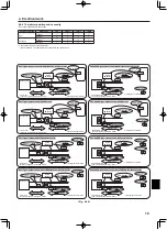
Notes: 1. Wiring size must comply with the applicable local and national codes.
2.
FTC4 (Master) unit/outdoor unit connecting cords shall not be lighter
than polychloroprene sheathed flexible cord. (Design 60245 IEC 57)
FTC4 (Master) unit power supply cords shall not be lighter than
polychloroprene sheathed flexible cord. (Design 60227 IEC 53)
3. Install an earth longer than other cables.
4. Please keep enough output capacity of power supply for each
individual heater. Insufficient power supply capacity might cause
chattering.
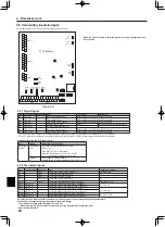
1
High voltage cables (OUTPUT)
2
Low voltage cables (INPUT)
3
Wireless receiver’s cable
4
Thermistor cables
5
Power cables
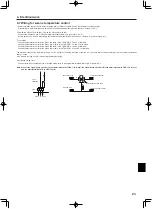
TB2
Clamps
Slot
TB1
Clamp
Clamps
1
2
3 4 5
Notes: 1. Do not run the low voltage cables through a slot that the high voltage cables go through.
2. Do not run other cables through a slot that the wireless receiver’s cable goes through.
3. Do not bundle power cables together with other cables.
4. Bundle cables as figure above by using clamps.
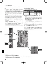
*1 If the installed earth leakage circuit breaker does not have an over-current protection function, install a breaker with that function along the same power line.
*2 Affix label B that is included with the manuals near each wiring diagram for FTC4 (Master) and outdoor units.
<Fig. 4.1.4> Wiring for PAC-IF052B-E
<3 phase>
<1 phase>