


4
86.7
22
10
422
338.5
368
(12.5)
12.5
393
:
5
:
12
72.4
288.8
207
22
10
254.4
(12.5)
229.4
12.5
:
12
:
5
2.3. Installing the FTC4 unit (Fig. 2.3.1, 2.3.2, 2.3.3, 2.3.4)
1. Remove 2 screws (
A
Screw) from FTC4 unit and remove the cover. (See Fig.
2.3.4)
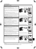
2. Install the 4 screws (locally supplied) in the 4 holes (
C
Hole).
w
To prevent the unit from falling off the wall, select the appropriate screws (locally
supplied) and secure the base horizontally to the appropriate wall location.
(See Fig. 2.3.2)
A
Screw
B
Cover
C
Hole for installation
D
Screw
Note: Do not remove the screws
D
as the screws are the component parts of the
cover and are not used for the installation of cover.
Weight
*** kg + ACCESSORIES *** kg
Allowable ambient temperature
0 to 35°C
Allowable ambient humidity
80% RH or less
2.2. Choosing the FTC4 unit installation location
• Do not install the FTC4 units outdoors as it is designed for indoor installation
only. (The FTC4 circuit board and casing are not waterproof.)
• Avoid locations where the unit is exposed to direct sunlight or other sources of
heat.
• Select a location where easy wiring access to the power source is available.
• Avoid locations where combustible gases may leak, be produced, flow, or accu
-
mulate.
• Select a level location that can bear the weight and vibration of the unit.
• Avoid locations where the unit is exposed to oil, steam, or sulfuric gas.
• Do not install in location that is hot or humid for long periods of time.
Optional extras
• Wireless Remote Controller
PAR-WT50R-E
• Wireless Receiver
PAR-WR51R-E
• Remote sensor
PAC-SE41TS-E
2. Installing the FTC4 unit
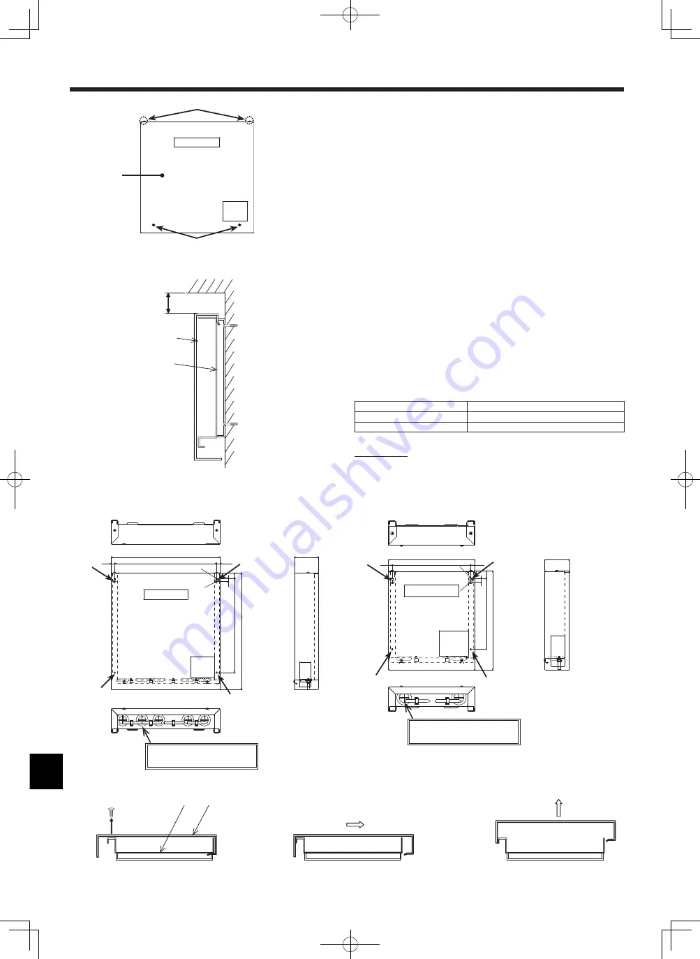
<Fig. 2.3.4>
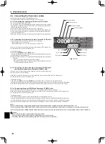
<Fig. 2.3.2>
Service space
<Fig. 2.3.1>
Top
Bottom
Pull the cover to the
front and remove it.
Slide the control box cover
until the bottom of the cover
comes into contact with the
bottom of the control box.
Remove the 2 screws
A
(control box cover screws).
Cover
Base
1
2
3
Top
Bottom
Top
Bottom
Front
Top
Wall
30 mm or more
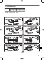
Cover
Base
5-ELECT WIRE INLET
When installed on a wall: Lower side
2-ELECT WIRE INLET
When installed on a wall: Lower side
<Fig. 2.3.3>
C
C
C
B
A
D
<FTC4 (Master) unit>
<FTC4 (Slave) unit>
C
C
C
C
C


