24
FTC4 Installation Manual
17
Cylinder & Hydraulic Components Install Guidance
Cold Mains Pipework
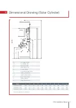
Run the cold main through the building to the place where the cylinder is to be installed. Take care not to run the
cold pipe near hot water or heating pipe work so that the heat pick up is minimized. Identify the cold water supply
pipe and fit an isolating valve (not supplied). A 22mm BS1010 stopcock can typically be used but a 22mm quarter
turn full bore valve would be better as it does not restrict the flow as much. Do not use a “screwdriver slot” or
similar valves. Make sure the connection to the cold feed of the cylinder incorporates a drain valve. Position the inlet
control just above the Temperature & Pressure Relief Valve (TPRV) mounted on the side of the cylinder. This ensures
that the cylinder does not have to be drained down in order to service the inlet control set. Ensure that the arrow
points in the direction of the water flow. Select a suitable position for the expansion vessel. Mount it to the wall
using the bracket provided. Use the hose to connect to the inlet control group.
Balance Cold Connection
If there are to be showers, bidets or monobloc taps in the installation then a balanced cold supply is necessary.
There is a 22mm balanced connection on the inlet control group.
Hot Water Pipework
Run the first part of the hot water distribution pipework in 22mm. This can be reduced to 15mm and 10mm as
appropriate for the type of tap etc. Your aim should be to reduce the volume of the hot draw off pipework to a
practical minimum so that the time taken for the hot water is as quick as possible. Do not use monobloc mixer taps
or showers if the balanced cold connection is not utilised outlets of this type can back pressurize the unit and result
in discharge. Ensure that the top of the expansion vessel is accessible for servicing.
Primary Connections
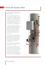
Ensure that the manifold for the primary flow pipework is moved from its transport position, the same applies to the
circulation pump and TF1 filter, once all components are in the correct position all factory connections should be
tightened. Connect the primary pipework at the inlet side of pump one on the flow and the return just below the TF1
compact filter. The primary circuit is positively pumped. The primary circuit can be open vented or sealed with up to
a maximum pressure of 3.5 bar. If you seal the primary circuit an expansion vessel and pressure relief valve is
required. Effective thermostatic control of both the primary circuit and the cylinder is incorporated into the FTC4
circuit board and corresponding thermistors, THW1, THW2 and THW5. The primary coil is intended for connection
of Ecodan
®
air source heat pumps only, the secondary coil (where included) is intended for solar thermal input.
Although it is in theory possible to use other heat sources it is important to note that uncontrolled heat sources
are not suitable.
Secondary Circulation
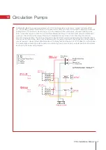
The Mitsubishi Electric pre-plumbed cylinder can be used with a secondary circulation pump. An appropriate WRAS
approved bronze circulator should be used in conjunction with a non-return valve to prevent backflow. On large
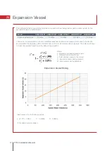
secondary circulation systems it may be necessary to incorporate an extra expansion vessel into the circuit to
accommodate the increased system water volume, details of how to calculate this are found later in this manual.
Efficient control of any secondary circulation pump fitted is essential, to leave the circulation pump on constantly will
cause the cylinder losses to increase dramatically and excessive hot water heat ups using the Ecodan
®
to occur, if
timed hot water heat ups are being used then a lack of hot water is another impact of poor secondary return pump
control. Timing the secondary return pump to run at times of peak hot water usage provides a slightly more efficient
method of controlling the secondary return pump. The most efficient way to control the secondary return pump is to
ensure that it only runs when required, i.e. when the bathroom is occupied, this can be achieved through use of
passive infra-red sensors. In any case all secondary return pipework should be heavily insulated, with an insulation
of at least the same thermal quality as that used on the primary pipework (thermal conductivity = 0.04W/m.K or less
at 0ºC). A secondary return boss is fitted as standard on 210, 250 and 300L. On smaller sizes tee in between the
cold feed pipe above the drain and the hot water draw off before the first outlet.
Summary of Contents for Ecodan HUS210FTC4ST
Page 2: ......
Page 8: ...5 Pipework Configuration 8 FTC4 Installation Manual ...
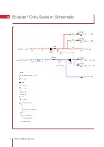
Page 20: ...20 FTC4 Installation Manual 14 Ecodan Only System Schematic ...
Page 83: ......


