

40
FTC4 Installation Manual
24
Electrical Installation
(continued)
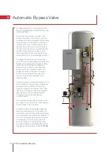
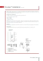
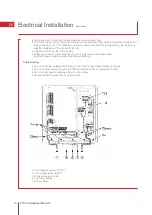
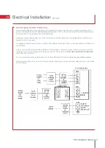
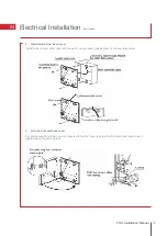
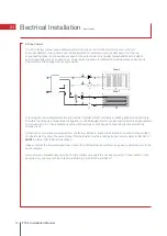
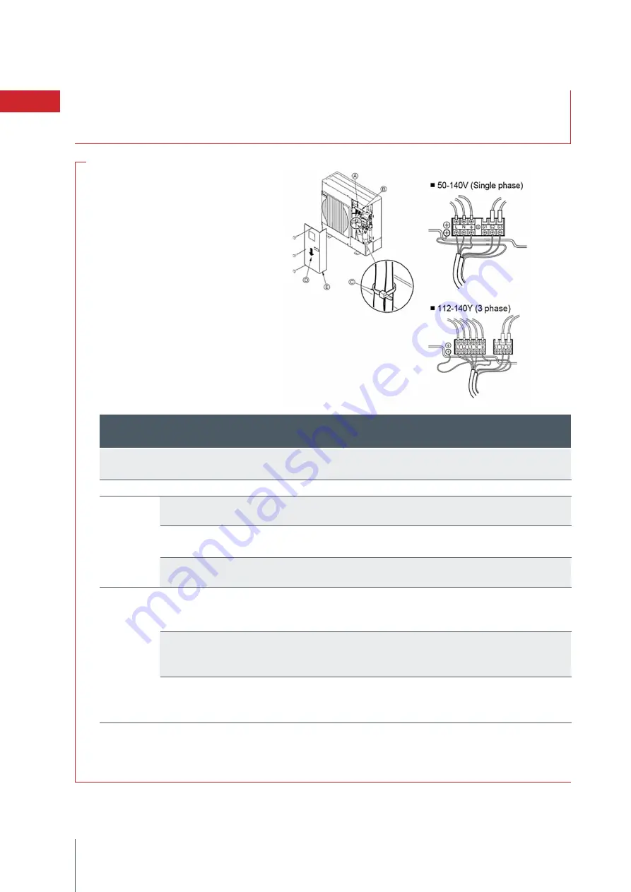
A.
Earth terminal
B.
Terminal block
C.
Clamp
D.
Service panel
E.
Wire the cables so
that they do not contact
the centre of the service
panel
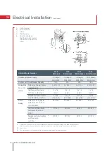
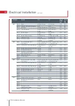
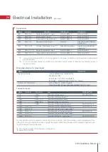
Outdoor unit power supply
~/N (single),
~/N (single),
~/N (single),
3N (3 phase),
50Hz, 230V
50Hz, 230V
50Hz, 230V
50Hz, 415V
Outdoor unit Circuit Breaker Capacity
*
1
16 A
32 A
40 A
16 A
Outdoor unit power supply
3 x Min. 2.5
3 x Min. 4
3 x Min. 6
5 x Min. 2.5
including earth
Interface unit/flow temp.
*
2
2 x 1.5
2 x 1.5
2 x 1.5
3 x 1.5
controller– outdoor unit
(polar)
(polar)
(polar)
(polar)
Remote controller-Interface
2 x 0.3
2 x 0.3
2 x 0.3
2 x 0.3
unit/ Flow temp. controller
(non-polar)
(non-polar)
(non-polar)
(non-polar)
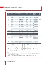
Outdoor unit L-N (single)
*
3
AC 230 V
AC 230 V
AC 230 V
AC 415 V
Outdoor unit L1-N, L2-N,
L3-N (3 phase)
Interface unit/Flow temp.
*
3
DC 24 V
DC 24 V
DC 24 V
DC 24 V
controller-outdoor unit
S2-S3
Remote controller-Interface *
3
DC 12 V
DC 12 V
DC 12 V
DC 12 V
unit/Flow temp.
controller
PUHZ-
HW140YHA(2)-BS
PUHZ-
HW140VHA(2)-BS
PUHZ-
W85VHA(2)-BS
PUHZ-
W50VHA-BS
Wiring Wire
No. x size
(mm²)
Circuit
Rating
Outdoor Model Number
*1.
A breaker with at least 3.0 mm contact separation in each pole shall be provided. Use earth leakage breaker
(NV). The breaker shall be provided to ensure disconnection of all active phase conductors of the supply.
*2.
Max. 120 m
*3.
The values given in the table above are not always measured against the ground value.
Summary of Contents for Ecodan HUS210FTC4ST
Page 2: ......
Page 8: ...5 Pipework Configuration 8 FTC4 Installation Manual ...
Page 20: ...20 FTC4 Installation Manual 14 Ecodan Only System Schematic ...
Page 83: ......


