
28
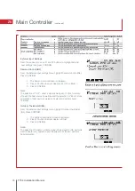
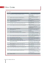
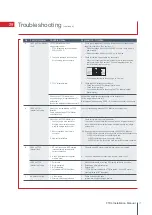
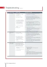
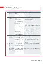
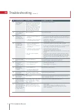
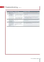
Error Codes
(continued)
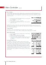
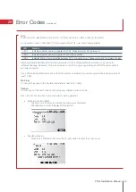
Note:
To cancel error codes please switch system off (Press button E, on Main Controller, for 3 secs).
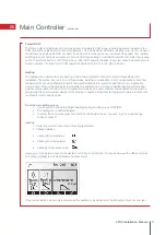
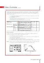
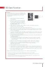
For description of each LED (LED1 to 3) provided on the FTC4, refer to the following table.
After completing installation and the wiring and piping of the local application and outdoor units, check for
refrigerant leakage, looseness in the power supply or control wiring, wrong polarity, and that the power cable is
securely connected.
Use a 500-volt megohmmeter to check that the resistance between the power supply terminals and ground is at
least 1.0M
Ω
.
Warning:
Do not use the system if the insulation resistance is less than 1.0M
Ω
.
Caution:
Do not carry out this test on the control wiring (low voltage circuit) terminals.
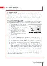
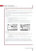
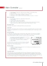
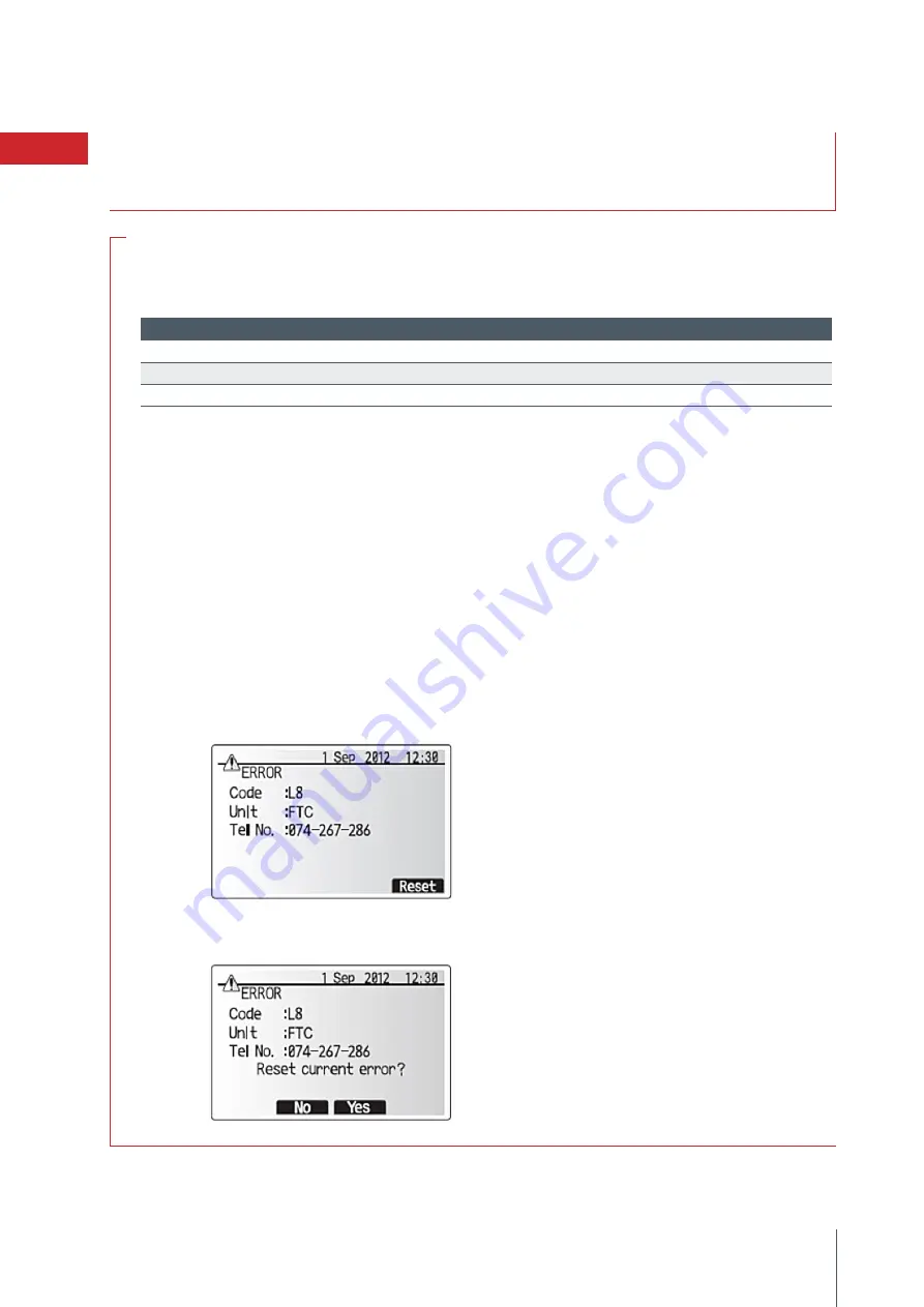
When an error occurs when power is applied or during operation
•
Indication of error details
The code, unit, address, and telephone number are displayed.
The telephone number is displayed if registered.
•
Resetting the error
Press the F4 (RESET) button, and the F3 (Yes) button to reset the current error.
69
FTC4 Installation Manual
LED 1
Indicates whether power is supplied to FTC4. Make sure this LED is always lit
LED 2
Indicates whether power is supplied to the main controller.
LED 3
Indicates state of communication between FTC4 and outdoor unit. Make sure this LED is always blinking
LED
Meaning
Summary of Contents for Ecodan HUS210FTC4ST
Page 2: ......
Page 8: ...5 Pipework Configuration 8 FTC4 Installation Manual ...
Page 20: ...20 FTC4 Installation Manual 14 Ecodan Only System Schematic ...
Page 83: ......


