Graphic Operation Terminal GOT-F900
Test Mode 13
13-7
13.5
Communication monitor (F940GOT, F940WGOT)
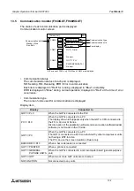
The status of each communication port is displayed.
Communication monitor screen
•
Communication status
The communication status of each port is displayed.
SD: Sending, RD: Receiving, ERR: Error in communication
Each item is displayed in "Red" for running, displayed in "Blue" on standby.
ERR is displayed in "Blue" during normal operation; displayed in "Red" at the time of error
occurrence.
•
Communication type
The name of units used for communication are displayed.
Display item
Display
Connected to
GOT
⇔
PLC
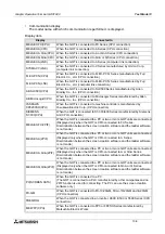
When the GOT is connected to the PLC
PC
⇔
PLC
When the GOT is connected to a PC
The display shown left appears only when the GOT is CPU-connected to
the FX, A, QnA or Q Series.
Discrimination of the application software (screen creation software/ladder
software) is not made on the PC side.
GOT
⇔
PC
When the GOT is connected to a PC
The GOT is connected to a PLC manufactured by other companies or units
not having a 2PIF function.
The PC can use the screen creation software only.
BARCODE
⇔
PLC
When a bar code reader is connected
GOT
⇔
PRINTER
When a printer is connected
GOT
⇔
GENERAL-
PUPOSE UNITS
When the GOT is connected to a microcomputer board (general-purpose
unit)
GOT
⇔
GOT
When two or more GOT units are connected
NO FUNCTION
Not connected to any units
[ Screen list ]
END
Communication status
Standby: Blue
Run: Red
SD
RD
ERR
COM1
SD
RD
ERR
COM2
SD
RD
ERR
GOT
⇔
PLC
MELSEC-FX(CPU)
No error
GOT ( Printer
No error
GOT
⇔
PLC
PC(SCREEN DATA)
No error
Communication type
Communication with
Error display
COM0
In the case of F940, only COM0 and COM2 are displayed.
Summary of Contents for F930GOT-BWD
Page 1: ...OPERATION MANUAL GOT F900 ...
Page 4: ...Graphic Operation Terminal GOT F900 ii ...
Page 6: ...Graphic Operation Terminal GOT F900 iv ...
Page 14: ...Graphic Operation Terminal GOT F900 Contents xii ...
Page 16: ...Graphic Operation Terminal GOT F900 Manual configuration and various data 2 MEMO ...
Page 30: ...Graphic Operation Terminal GOT F900 Introduction 1 1 14 MEMO ...
Page 34: ...Graphic Operation Terminal GOT F900 Outside dimensions 3 3 2 MEMO ...
Page 38: ...Graphic Operation Terminal GOT F900 Part names 4 4 4 MEMO ...
Page 42: ...Graphic Operation Terminal GOT F900 Installation 5 5 4 MEMO ...
Page 90: ...Graphic Operation Terminal GOT F900 Creation of Display Screens 8 8 32 MEMO ...
Page 154: ...Graphic Operation Terminal GOT F900 Alarm Mode 12 12 14 MEMO ...
Page 164: ...Graphic Operation Terminal GOT F900 Test Mode 13 13 10 MEMO ...
Page 174: ...Graphic Operation Terminal GOT F900 Connection to Bar Code Reader 15 15 2 MEMO ...
Page 180: ...Graphic Operation Terminal GOT F900 Screen Hard Copy Function 16 16 6 MEMO ...
Page 320: ...Graphic Operation Terminal GOT F900 Creation of Display Screen GT Designer 20 20 46 MEMO ...
Page 341: ......


