Graphic Operation Terminal GOT-F900
Changeover of Display Screen (FX-PCS-DU/WIN-E) 19
19-16
19.7
Application of screen changeover
This paragraph describes an application example of screen changeover.
Example of screen changeover by touch key in the GOT and word device in the PLC
•
In the example below, screen changeover by touch key and screen changeover by word
device in the PLC are used together.
-
Common setting for all screens
The "Change Screen" object is set so that screen No. 0 is displayed when the MENU key
is pressed.
This setting is suitable to read a certain screen such as the menu screen.
Characters for menu items are displayed using the "Text" object.
-
Setting for individual screen
•
Screen No. 0 is created, and the "Change Screen"
object is set as follows.
•
It is set so that screen No. 1 is displayed by a data
register (word device) in the PLC.
The initial value of the data register for screen
changeover is D0.
If "Bit Device" is not specified, both "Control
Input" and "Bit Device" are not specified.
A c c o r d i n g l y, t h e s c r e e n i s c h a n g e d o v e r
immediately by a data register in the PLC.
For the condition to make screen changeover by
data register effective, enter "Control Input" or "Bit
Device" as shown in the program example 1 in the
next page.
Continued in sequence program examples on the next page.
Condition
Screen
No.
(Direct)
Save Current
Screen
Control
Input
Bit Device
1
Touch key
No. 0
Not specified
1
Not effective
2
Touch key
No. 1
Not specified
2
Not specified
Condition
Screen
No.
(Direct)
Save Current
Screen
Control Input Bit Device
1
Not specified
M100
PLC data
register
Not effective
Condition
Screen
No.
(Direct)
Save Current
Screen
Control
Input
Bit Device
1
Touch key
No. 50
Not specified
0
Not effective
W h e n t h e M E N U k ey i s
pressed, the menu screen
(screen No. 0) is displayed.
"ST. 1" key
When a sequence program is executed,
screen No. 10 or 20 is displayed.
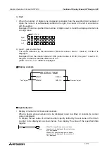
Screen No. 0
MONITOR
MONITOR
* MENU *
To screen
No. 2
Screen No. 1
PROCESSING
When the MENU key is pressed, screen
No. 0 is displayed.
"ST. 2" key
ST. 1
ST. 2
"STATION 1" KEY MONITOR
Summary of Contents for F930GOT-BWD
Page 1: ...OPERATION MANUAL GOT F900 ...
Page 4: ...Graphic Operation Terminal GOT F900 ii ...
Page 6: ...Graphic Operation Terminal GOT F900 iv ...
Page 14: ...Graphic Operation Terminal GOT F900 Contents xii ...
Page 16: ...Graphic Operation Terminal GOT F900 Manual configuration and various data 2 MEMO ...
Page 30: ...Graphic Operation Terminal GOT F900 Introduction 1 1 14 MEMO ...
Page 34: ...Graphic Operation Terminal GOT F900 Outside dimensions 3 3 2 MEMO ...
Page 38: ...Graphic Operation Terminal GOT F900 Part names 4 4 4 MEMO ...
Page 42: ...Graphic Operation Terminal GOT F900 Installation 5 5 4 MEMO ...
Page 90: ...Graphic Operation Terminal GOT F900 Creation of Display Screens 8 8 32 MEMO ...
Page 154: ...Graphic Operation Terminal GOT F900 Alarm Mode 12 12 14 MEMO ...
Page 164: ...Graphic Operation Terminal GOT F900 Test Mode 13 13 10 MEMO ...
Page 174: ...Graphic Operation Terminal GOT F900 Connection to Bar Code Reader 15 15 2 MEMO ...
Page 180: ...Graphic Operation Terminal GOT F900 Screen Hard Copy Function 16 16 6 MEMO ...
Page 320: ...Graphic Operation Terminal GOT F900 Creation of Display Screen GT Designer 20 20 46 MEMO ...
Page 341: ......


