Graphic Operation Terminal GOT-F900
Changeover of Display Screen (GT Designer) 21
21-3
21.3
Changeover of base screen (changeover from PLC)
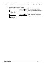
The No. of a screen to be displayed can be specified using the current value of a word device
(D, T or C) in the PLC.
The word device can be set in "Change Screen" in "Common Setting" in the screen creation
software. By performing this setting only once, a screen to be displayed next can be specified
from the PLC for any screen as the setting is effective to all screens.
21.3.1
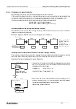
Outline of changeover of base screen
•
Base screen changeover settings can be performed using the screen creation software.
Setting for screen changeover
Base screen
: Whose screen No. is equivalent to the current value of a word device D,
C or T (initial value = D0)
Overlap window 1:Screen overlaying the base screen (initial value = none)
Overlap window 2:Screen overlaying the overlap window 1 (For screen overlay, refer to
Paragraph 9.5.2.)
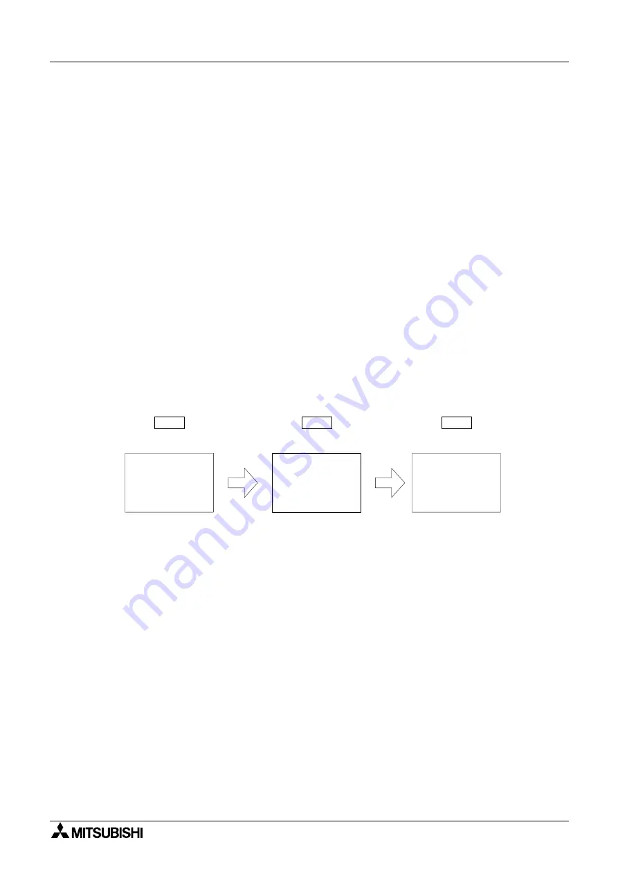
Example: When the word device D0 is used to change over the base screen
•
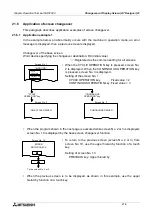
When the display screen is changed over using a touch key as described in the next
paragraph, a screen No. specified by the touch key is stored as the current value of the word
device specified for "changeover of the base screen".
However, when a system screen (No, 1001 to 1030) is displayed using a touch key, the
screen No. is not stored. For changeover to a system screen, refer to Paragraph 21.5.
n
n
n
n
Important point
Word device used to specify the base screen:
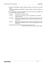
If a word device used to specify the base screen, is not located in the battery backup area
(keep area, latch area), when the power of the PLC is turned OFF or when the PLC assumes
stop status, the current value of the word device as 0. In this case, the error message
"DISPLAY SCREEN IS NOT AVAILABLE." is displayed as the user screen starts from screen
No. 1. It is recommended to use a word device in the battery backup area.
Screen No. 1 is displayed.
D0: Current value
1
10
20
Screen No. 10 is displayed.
Screen No. 20 is displayed.
Summary of Contents for F930GOT-BWD
Page 1: ...OPERATION MANUAL GOT F900 ...
Page 4: ...Graphic Operation Terminal GOT F900 ii ...
Page 6: ...Graphic Operation Terminal GOT F900 iv ...
Page 14: ...Graphic Operation Terminal GOT F900 Contents xii ...
Page 16: ...Graphic Operation Terminal GOT F900 Manual configuration and various data 2 MEMO ...
Page 30: ...Graphic Operation Terminal GOT F900 Introduction 1 1 14 MEMO ...
Page 34: ...Graphic Operation Terminal GOT F900 Outside dimensions 3 3 2 MEMO ...
Page 38: ...Graphic Operation Terminal GOT F900 Part names 4 4 4 MEMO ...
Page 42: ...Graphic Operation Terminal GOT F900 Installation 5 5 4 MEMO ...
Page 90: ...Graphic Operation Terminal GOT F900 Creation of Display Screens 8 8 32 MEMO ...
Page 154: ...Graphic Operation Terminal GOT F900 Alarm Mode 12 12 14 MEMO ...
Page 164: ...Graphic Operation Terminal GOT F900 Test Mode 13 13 10 MEMO ...
Page 174: ...Graphic Operation Terminal GOT F900 Connection to Bar Code Reader 15 15 2 MEMO ...
Page 180: ...Graphic Operation Terminal GOT F900 Screen Hard Copy Function 16 16 6 MEMO ...
Page 320: ...Graphic Operation Terminal GOT F900 Creation of Display Screen GT Designer 20 20 46 MEMO ...
Page 341: ......


