background image

[Startup and Maintenance Precautions] 

 WARNING 

  Do not touch any terminal while power is on. Doing so can cause an electric shock or malfunction. 


Be sure to shut off the external power supply for the system in all phases before cleaning the product or 

retightening the terminal screws, the mounting screws of the connector, or the fixing screws of the product. 

Failure to do so may result in an electric shock, or cause the product to fail or malfunction. Undertightening 

can cause the product to drop, short circuit, or malfunction. Overtightening can damage the screw and/or 

product, causing the product to drop, short circuit, or malfunction.


[Startup and Maintenance Precautions] 

 CAUTION 

  Do not disassemble or modify the modules. Doing so may cause failure, malfunction, injury, or a fire. 

  Use any radio communication device such as a cellular phone or PHS (Personal Handy phone System) 

more than 25cm (9.85 inches) away in all directions from the programmable controller, this product. 

Failure to do so may cause malfunction. 

  Shut off the external power supply for the system in all phases before mounting or removing the module. 

Failure to do so may cause the module to fail or malfunction or damage. 

  After the first use of the product, do not mount/remove the module, and the cable more than 50 times 

(IEC 61131-2 compliant) respectively. Exceeding the limit of 50 times may cause malfunction. 

  Startup and maintenance of a control panel must be performed by qualified maintenance personnel with 

knowledge of protection against electric shock. Lock the control panel so that only qualified maintenance 
personnel can operate it. 

  Before handling the module, touch a grounded metal object to discharge the static electricity from the 

human body. 

Failure to do so may cause the module to fail or malfunction. 


[Disposal Precautions] 

 CAUTION 


When disposing this product, treat it as industrial waste.


[Transportation Precautions] 

 CAUTION 

  Avoid the shock that exceeds the shock resistance described in the general specifications during 

transportation, as the product is a precision device. Failure to do so can cause the product to fail. 


If halogen-based materials (fluorine, chlorine, bromine, iodine, etc.) infiltrate into our products, the products 

will be damaged. Halogen-based materials are often included in fumigant, which is used to sterilize or 

disinfest wooden packages. Prevent residual fumigant components from being infiltrated into our products, or 

use an alternative sterilization or disinfection method (heat disinfection, etc.). Additionally, use the wooden 

package made of woods sterilized and protected against insects as a measurement.


Summary of Contents for FA-TH16XRA20S

Page 1: ...h this product only For programmable controller system safety precautions refer to the user s manual of the programmable controller used In this manual the safety precautions are classified into two levels WARNING and CAUTION WARNING Indicates that incorrect handling may cause hazardous conditions resulting in death or severe injury CAUTION Indicates that incorrect handling may cause hazardous con...

Page 2: ...current or an overcurrent caused by a load short circuit flows for a long time it may cause smoke and fire To prevent this configure an external safety circuit such as a fuse Configure a circuit to turn on the programmable controller and then the external power supply If the external power supply is turned on first an accident may occur due to an incorrect output or malfunction Design Precautions ...

Page 3: ...que range Undertightening can cause the product to drop short circuit or malfunction Overtightening can damage screws and or the product causing the product to drop short circuit or malfunction Be sure to shut off the external power supply for the system in all phases before installing or removing the product Failure to do so may damage the product or cause the product to malfunction or fail Do no...

Page 4: ... so may cause a malfunction When disconnecting a cable from the product do not pull the cable itself For a cable with connector hold the connector and pull it out For a cable connected to a terminal block loosen the terminal block screws before removing the cable Failure to do so may result in a malfunction or damage to the product or cable Before connecting the cables check the type of interface ...

Page 5: ...use of the product do not mount remove the module and the cable more than 50 times IEC 61131 2 compliant respectively Exceeding the limit of 50 times may cause malfunction Startup and maintenance of a control panel must be performed by qualified maintenance personnel with knowledge of protection against electric shock Lock the control panel so that only qualified maintenance personnel can operate ...

Page 6: ...res must issue an EC Declaration of Conformity and the products must bear a CE marking 1 Authorized representative in Europe The authorized representative in Europe is shown below Name Mitsubishi Electric Europe B V Address Mitsubishi Electric Platz 1 40882 Ratingen Germany 2 How to use the FA Goods in compliance with the EMC and Low Voltage Directives For information on how to conform to the EMC ...

Page 7: ...CATIONS 4 CONNECTED TARGET MODEL PLC MODULE CONNECTION CABLE 7 INSTALLATION METHOD 11 PRECAUTIONS 12 COVERAGE OF WARRANTY 13 EXCLUSION FROM LIABILITY FOR OPPORTUNITY LOSS AND SECONDARY LOSS FOR YOUR SAFETY Japanese manual number 50D FA9010 009 This manual confers no industrial property rights or any rights of any other kind nor does it confer any patent licenses Mitsubishi Electric Corporation can...

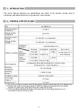
Page 8: ...tinuous vibration 5 to 8 4Hz 1 75mm 8 4 to 150Hz 4 9m s2 0 5G Shock resistance Compliant with JIS B 3502 and IEC61131 2 147m s2 15G 3 times each in X Y and Z directions Operating atmosphere No corrosive gas Operating altitude 1 2 000m or lower Installation location Inside the control panel Overvoltage category 2 II or lower Pollution level 3 2 or lower 1 Do not use or store the module under the at...

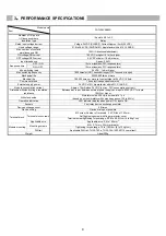
Page 9: ...ernal supply power 24 VDC 10 ripple factor within 5 CLASS 2 Module consumption current Approx 10mA when 24 VDC not inc PLC consumption current Dielectric withstand voltage insulation resistance Between eac input between external power supply and inputs 2500 VAC 1 minute 10MΩ or higher Withstand noise Simulator noise 500 Vp p noise width 1 μs based on noise simulator with noise frequency of 25 to 6...

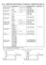
Page 10: ...tor type A1SX41 Note 2 A1SX41 S1 A1SX41 S2 A1SX42 Note 2 A1SX42 S1 A1SX42 S2 FA CBL FM2V Note 1 FA CBL FM2LV Note 1 A1SH42 Note 2 A1SH42 S1 A1SH42P Note 2 A1SH42P S1 Input side FA CBL FM2V Note 1 FA CBL FM2LV Note 1 CC Link connector type AJ65SBTCF1 32D AJ65BTC1 32D At positive common FA CBL FM2H Note 1 FA CBL FM2LH Note 1 MELSEC F Series MELSEC iQ F Series Connector type FX2NC 16EX FX2NC 32EX FX3...

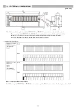
Page 11: ...ries module from our MEEFAN website and replace the sheet as needed URL http www mee co jp sales fa meefan parts cad fa_goods cad_list html Terminal block symbol paper MELSEC iQ R and MELSEC Q series Hexadecimal Note 5 Front Back MELSEC iQ F and MELSEC F series Octal Downloadable from our website Front Back Note 5 This sheet is attached to the module Note 6 When using the MELSEC iQ F or MELSEC F s...

Page 12: ...12 6 MODULE MOUNTING ORIENTATION Horizontal mounting Vertical mounting ...

Page 13: ...1 1 When cable with terminal block is used Attach the terminal block securely to the PLC module with attachment screws Programmable controller module QX40 other Insert the connector to the back and then fully secure the connector with a clip Connection cable FA CBL TMV20 Switch etc ...

Page 14: ... Switch etc Insert the connector to the back and then fully secure the connector with a clip Programmable controller module QX40 other Attach the power wires securely to the PLC module terminal block Connection cable FA CBL M20 FA CBL YM20 ...

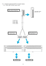
Page 15: ...tor to the programmable controller module using the mounting screws Programmable controller module QX41 other Insert the connector to the back and then fully secure the connector with a clip Connection cable FA CBL FM2V FA CBL FM2LV FA CBL FM2H FA CBL FM2LH Insert the connector to the back and then fully secure the connector with a clip Switch etc Switch etc ...

Page 16: ...16 7 2 2 When a 20P connector cable is used ...

Page 17: ...17 8 EXTERNAL CONNECTION EXAMPLE 9 HOW TO DISMOUNT AND SET THE DEVICE REMOVE ...

Page 18: ...ESS TERMINALS Solderless terminal dimensions Unit mm Round non insulated solderless terminal Round insulated solderless terminal Y non insulated solderless terminal Y insulated solderless terminal Terminal block shape Unit mm ...

Page 19: ...3 Failure that could have been avoided if when our product was assembled into customer s device safeguards defined by legal regulations applicable to customer s device or functions or structures considered standard by the industry had been provided 4 Failure recognized as preventable if the consumed products specified in instruction manuals etc were normally maintained or replaced 5 Replacement of...

Page 20: ...tation atomic power electric power aerospace or medical applications please contact your nearest Mitsubishi sales representative Although this product was manufactured under conditions of strict quality control the product shall be systematically provided with backup and fail safe functions when it is used in facilities where breakdowns of the product are likely to cause a serious accident or dama...

Reviews: