255
2
P
ARAM
ETE
R
PARAMETER
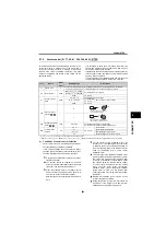
(2) Control method switching by external
terminals (RT signal, X18 signal)
1) FR-A700 series
The switching of the control method (V/F control,
Advanced magnetic flux vector control, Real
sensorless vector control and vector control) by the
external terminal may be made in either of the
following two ways: switching by the second function
selection signal (RT), or V/F switching signal (X18).
Two types of control method can be switched with the
RT signal by setting the type of motor to be used as
second motor in [
Pr. 450 Second applied motor
] and
control method of the motor in [
Pr. 451 Second motor
control method selection
]. Turn ON the RT signal to
select the second function. Other second function is
also made valid.
For switching by the X18 signal, setting [
Pr. 81
Number of motor poles
= 12, 14, 16, 18, 20] and turning
the X18 signal ON switches the currently selected
control method (Advanced magnetic flux vector
control, Real sensorless vector control or vector
control) to V/F control. In this case, use this signal
only for changing the control method of one motor
since second function as electronic thermal relay
characteristic, etc. can not be changed. (Use the RT
signal to change the second function.)
For the terminal used for X18 signal input, set 18 in
any of [
Pr. 178 to Pr. 189 Input terminal function
selection
] to assign the function.
2) FR-E700, D700 series
To change the control method (V/F control to
Advanced magnetic vector control or General
purpose vector control) with an external terminal, use
V/F switch signal (X18).
Turning X18 signal ON switches control from
Advanced magnetic vector control or General-
purpose magnetic vector control to V/F control.
For the terminal to input X18 signal, assign the
function by setting "18" to any of [
Pr.178 to 184 Input
terminal function selection
].
Switch the control method using external terminal
(X18 signal) during an inverter stop. If control method
between V/F control and General-purpose magnetic
flux vector control is switched during the operation,
the actual switchover does not take place until the
inverter stops. In addition, if control method is
switched to V/F control during the operation, only
second function becomes valid as V/F control and
second functions are selected simultaneously in V/F
control.
(3) Switching the control method from the
external terminal (MC signal)
When [
Pr. 800 = 12, 2
] and [
Pr. 451 = 12
], speed
control is selected when the control mode switching
signal (MC) is OFF, and torque control is selected
when the signal is ON under Real sensorless vector
control or vector control. Switching between speed
control and torque control is always enabled
independently of whether the motor is at a stop or
running or the DC injection brake operation (pre-
excitation).
Under vector control, speed control/position control
switchover and torque control/position control
switchover can be made by setting [
Pr. 800
= 4, 5].
Speed control/position control switchover and torque
control/position control switchover is made when
frequency decreases to or below the [
Pr. 865 Low
speed detection
] setting.
For the terminal used for MC signal input, set 26 in
any of [
Pr. 178 to Pr. 189 Input terminal function
selection
] to assign the function.
When an analog input terminal (terminal 1,4) is used
for torque limit, torque command, etc., terminal
functions also switch if control mode is switched.
For the terminal function in different control modes,
refer to page 43.
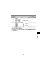
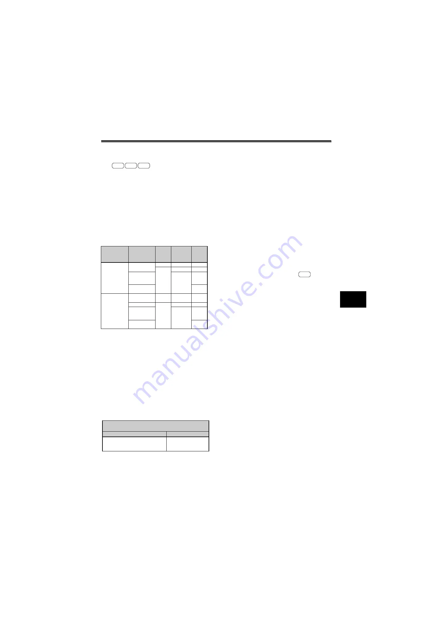
First Motor
Control Method
(RT signal-OFF)
Second Motor
Control Method
(RT signal-ON)
[
Pr. 450
]
Setting
[
Pr. 453
] and
[
Pr. 454
]
Setting
[
Pr. 451
]
Setting
V/F control
V/F control
9999
—
—
Other
than 9999
9999
—
Advanced
magnetic flux
vector control
Other than
9999
20, 9999
Real sensorless
vector control
10 to 12
Advanced
magnetic flux
vector control
Real sensorless
vector control
Vector control
Same control as
the first motor *
9999
—
—
V/F control
Other
than 9999
9999
—
Advanced
magnetic flux
vector control
Other than
9999
20, 9999
Real sensorless
vector control
10 to 12
* V/F control is selected when "12, 14, 16, 18, 20" is set in
[
Pr. 81
] and the X18 signal is ON. When the X18 signal is
not assigned, turning the RT signal ON selects V/F control
as the RT signal shares this function.
First motor control method ([
Pr. 80 = Motor capacity
],
[
Pr. 81 = 12, 14, 16, 18, 20
])
X18 (RT) signal-OFF
X18 (RT) signal-ON
Advanced magnetic flux vector control
Real sensorless vector control
Vector control
V/F control
A700
E700
D700
A700
Summary of Contents for FR-A700 Series
Page 245: ...279 2 PARAMETER PARAMETER MEMO ...
Page 440: ...474 PARAMETER MEMO ...
Page 522: ...556 SELECTION MEMO ...


