414
PARAMETER
(5) Parameter details
When ratio ([
Pr. 128
= "42, 43"]) is selected for
addition method, PID control
×
(ratio of main speed)
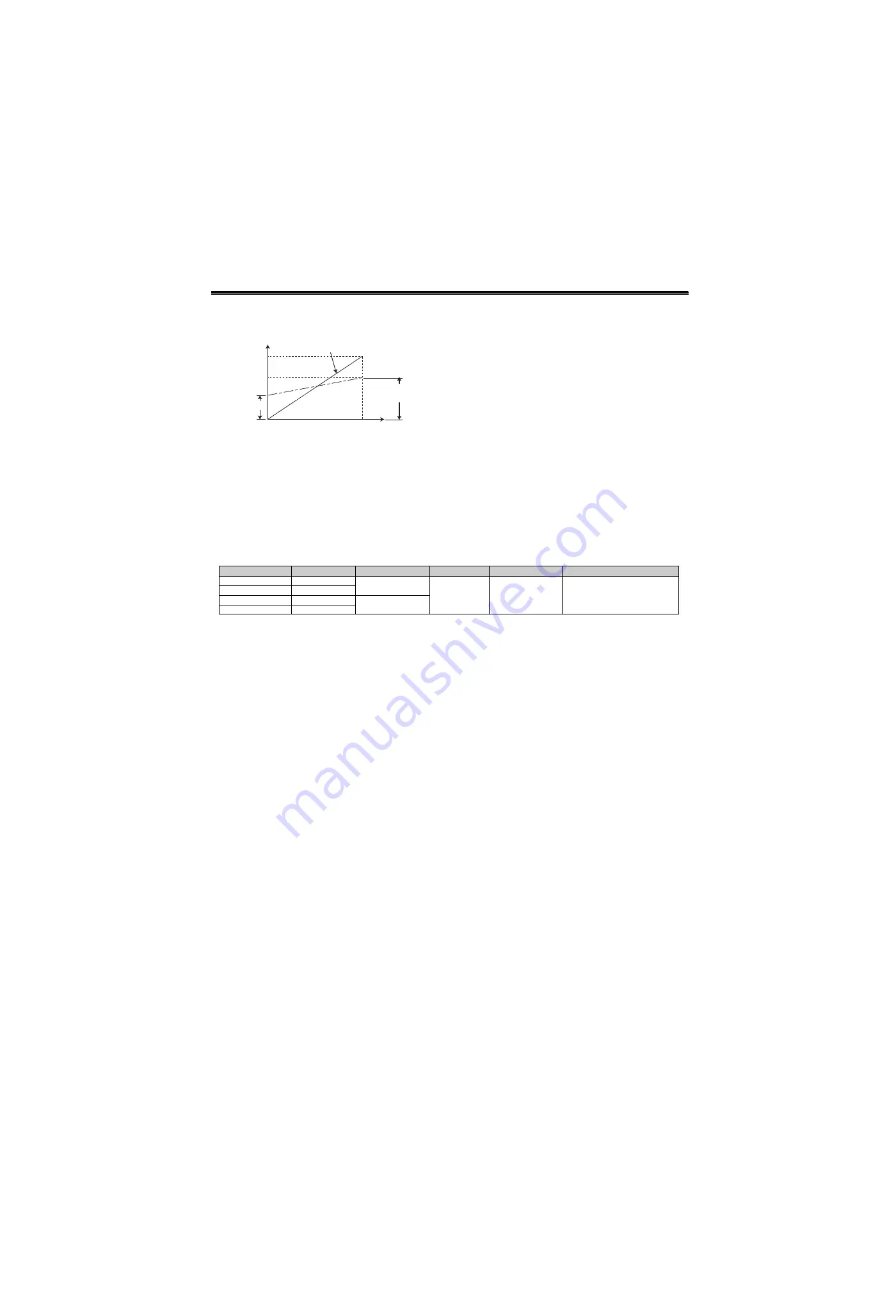
is added to the main speed. The ratio is determined
by the [
Pr. 125
Terminal 2 frequency setting gain
frequency
] and [
C2 (Pr. 902)
Terminal 2 frequency setting
bias frequency
]. The frequency setting signal is set to 0
to 60Hz in the range of 0 to 100% in the initial setting.
The ratio is (
×
100%) when the main speed is 60Hz
and (
×
50%) when 30Hz.
Even when C4 [(
Pr. 903
)] is set to other than 100%,
the frequency setting signal is considered as 100%.
Even when [C3 (
Pr. 903
)] is set to other than 0%, the
frequency setting signal is considered as 0%.
When [C2 (
Pr .902
)] is set to other than 0Hz, the
frequency setting signal is 0% when [C2 (
Pr. 902
)] is
less than the set frequency.
Turning X14 signal ON/OFF during operation by
assigning X14 signal results in the following
operation.
When X14 signal is ON: Uses output frequency
unchanged as the main speed command and
continues operation by dancer control.
When X14 signal is OFF: Ends dancer control
and continues operation at the set frequency.
Action of [
Pr. 129 PID proportional band
]
,
[
Pr. 130 PID
integral time
]
,
[
Pr. 131 PID upper limit
]
,
[
Pr. 132 PID
lower limit
]
,
[
Pr. 134 PID differential time
] is the same
as PID control. For the relationship of controlled
variable (%) of PID control and frequency, 0% is
equivalent to the set frequency of [
Pr. 902
] and 100%
to [
Pr. 903
] .
For the [
Pr. 133 PID action set point
] setting, set
frequency of [
Pr. 902
] is equivalent to 0% and [
Pr.
903
] to 100%. When
9999
is
set in
[
Pr. 133
], 50% is
the set point.
*1
PID control stops when RH, RM, RL, and REX signals
(for multi-speed operation) or JOG signal is input during
normal PID control. However, PID control continues
when those signals are input during dancer control since
these are treated as speed commands.
*2
The second acceleration/deceleration time set in [
Pr. 44,
45
] is the acceleration/deceleration time for the main
speed command during dancer control, and it does not
function as second function.
*3
Dancer control (PID control) is invalid when switchover
mode is selected with [
Pr. 79
=6].
*4
Speed command to terminal 4 by turning AU signal ON is
invalid during dancer control.
*5
Acceleration/deceleration of main speed command
follows the frequency increase/decrease made by analog
input. Therefore, the following situations may occur:
• SU signal may stay ON even though start signal is
switched ON/OFF. (Always in constant speed status)
• When the start signal is OFF, the DC brake does not
activate at the frequency set in [
Pr.10
], but at the smaller
frequency between [
Pr. 13
] setting or 0.5Hz.
• The value of "speed c PID control", which is
constantly changing, is displayed in the set frequency
monitor.
*6
The main speed setting frequency accelerates/
decelerates by the [
Pr. 44, 45
] settings. Output frequency
accelerates/decelerates by the [
Pr. 7, 8
] settings.
Therefore, when the set time in [
Pr.7, 8
] is longer than the
set time in [
Pr. 44, 45
], the set time in [
Pr. 7, 8
] is the
acceleration/deceleration time of the output frequency.
*7
Integral term is limited by the smaller value between
100% and the PID manipulated variable (%) converted
from the linear interpolated [
Pr.1 Maximum frequency
] by
[
Pr. 902, 903
].
Although the output frequency is limited by the minimum
frequency, the action of the integral term is not limited.
[
C2(Pr. 902)
]
Output frequency
0
Frequency setting signal
100%
Initial value
Bias
[
Pr. 125
]
Gain
[
Pr. 128
Setting]
PID Action
Addition Method
Set Point
Measured Value
Main Speed Command
40
Reverse action
Fixed
Pr. 133
Terminal 4
Speed command for each
operation mode
41
Forward action
42
Reverse action
Ratio
43
Forward action
Summary of Contents for FR-A700 Series
Page 245: ...279 2 PARAMETER PARAMETER MEMO ...
Page 440: ...474 PARAMETER MEMO ...
Page 522: ...556 SELECTION MEMO ...


