486
SELECTION
3.1.3
Starting torque and starting current of the motor
(common)
When the standard motor is full-voltage started with the
commercial power supply, the starting current is generally
about 6 to 7 times larger than the rated motor current and
the motor starting torque is approximately 150 to 250% of
the rated motor torque.
However, the starting and acceleration characteristics of
the motor used with the inverter are limited by the overload
current rating of the inverter used and are different from
those when the motor is full-voltage started with the
commercial power supply.
Since the motor is accelerated with the motor
starting acceleration current kept with the overload
current rating (150% of the rated output current (120% for
)) of the inverter, the starting torque and
acceleration torque are smaller than the commercial power
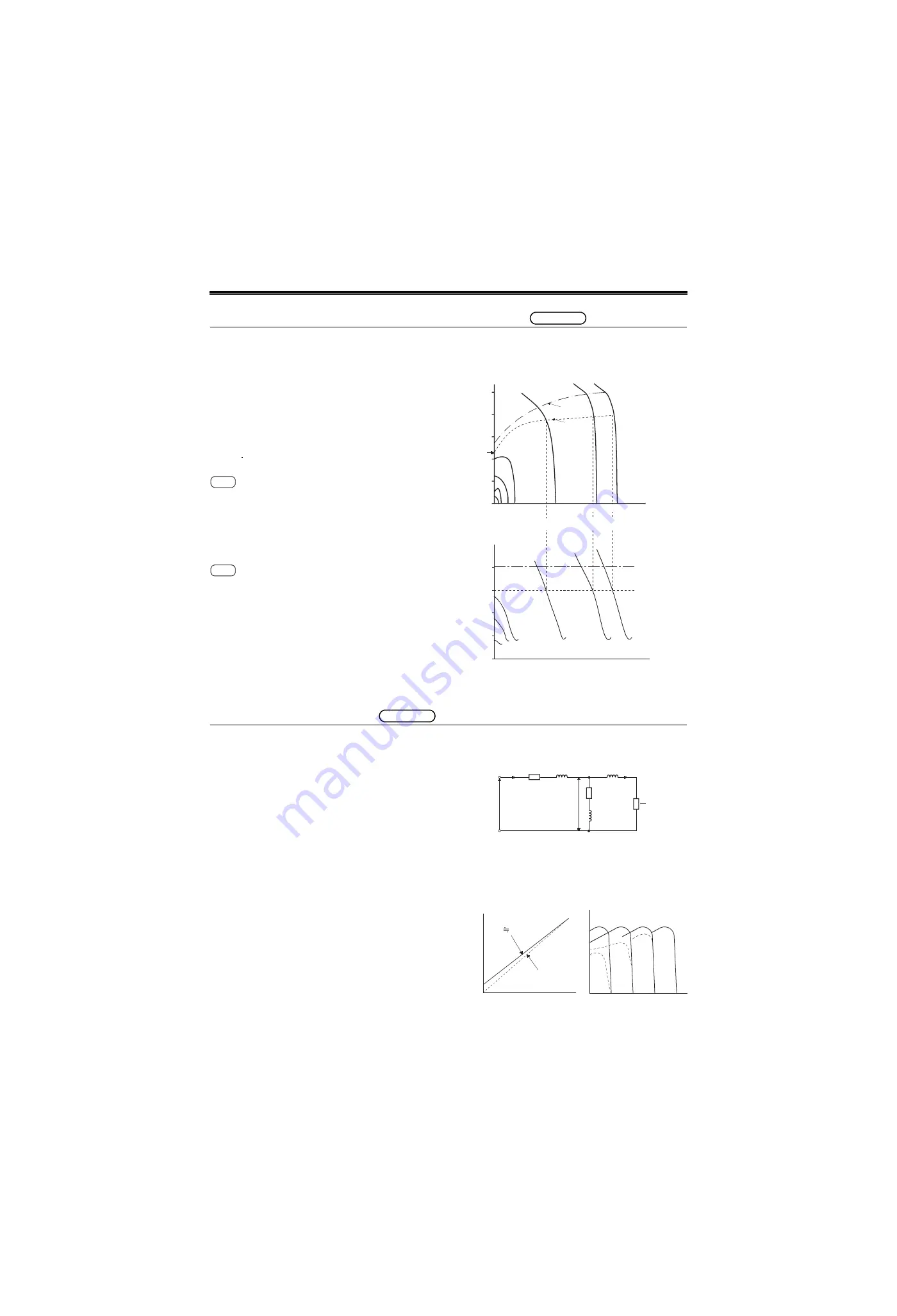
supply. Speed-torque and speed-current characteristic
examples of the standard motor are as shown in the figure
on the right. When the motor is used with the inverter of the
corresponding capacity, the torque at the speed
corresponding to the intersection of overload current rating
(150% of the rated inverter output current (120% for
)) and the current characteristics at each frequency
is the maximum torque (short-duration rated) generated by
the motor. In the example shown on the right, the starting
torque at the speed of 0 is 118% (point A).
When the capacity of the inverter used with the motor is
increased by one rank, the starting torque and maximum
torque increase in proportion to the rise in overload
capacity as shown on the right. When the starting torque
and acceleration torque are insufficient, it is effective to
increase the inverter capacity by one rank.
Changing in proportion to the square of the voltage, the
motor-generated torque is influenced by the inverter output
voltage.
Since the output voltage of the FR series inverter changes
in proportion to the change in input voltage (power supply
voltage) of the inverter, the motor speed varies, changing
the motor current.
3.1.4
Starting torque boost
(common)
The ideal constant-torque characteristic is provided when
the ratio of the inverter output voltage (V) to output
frequency (f) is as indicated by the broken line in the figure
on the right (terminal voltage and frequency) and the
torque characteristic in the constant V/f control area is as
indicated by the continuous line in the figure on the right
(torque characteristic). In the low frequency area, however,
since the air gap magnetic flux of the motor, i.e. E
1
/f, is
reduced by a voltage drop due to the primary resistance
(r
1
) of the induction motor as shown in the motor equivalent
circuit (refer to the figure on the right), the motor torque
drops as indicated by the broken line in the figure on the
right (torque characteristic).
To prevent the torque reduction at low frequencies,
compensate for the voltage drop of the primary resistance
to make the inverter output voltage compensation, as
indicated by the continuous line in the right figure (torque
characteristic). Therefore, the magnetic flux gap becomes
constant, and torque characteristic will be closer to the
constant torque characteristic on the right (torque
characteristic).
The FR series inverters have a function to adjust the
inverter output voltage (torque boost). When the starting
load torque is large, the primary motor current (l1) is higher
than in the equivalent circuit in right figure and E1 is
reduced by the voltage drop of the primary resistance (r1).
To compensate for this, the torque boost function raises the
inverter output voltage.
For details of the torque boost, refer to page 244.
Equivalent circuit of the motor
common
F700
F700
250
200
150
100
50
0
0
300
900
1500 1800
3 6 10
30
50
60Hz
A
Speed
(r/min)
220V 60Hz
SF-JR 1.5kW 4P
FR-A720-1.5K
Torque boost
standard
(initial setting)
One rank
higher capacity
Rated
capacity
Maximum
short-
duration
T
o
rque (%)
200
150
100
50
0
300
900
1500 1800
3 6
10
Current (%)
0
Speed
(r/min)
30
50
60Hz
One rank
higher capacity
Rated
capacity
V/F control speed-current characteristic
V/F control speed-torque characteristic
common
V
1
: Primary phase voltage
l
1
: Primary current
l
2
: Secondary current (value
converted to the primary side)
r
1
: Primary resistance
r
2
: Secondary resistance
(value converted to the
primary side)
r
M
: Iron loss resistance
x
M
: Exciting reactance
x
1
: Primary leak reactance
S
1
: Slip
x
2
: Secondary leak reactance
(value converted to the
primary side)
V
1
E
1
r
M
jx
M
l
1
r
1
jx
1
jx
2
r
2
S
1
l
2
Motor terminal
voltage, (V
1
) [V]
(E1/f constant)
(V
1
/f = constant)
Frequency, (f) [Hz]
Speed
Torque
Torque characteristic
Terminal voltage and frequency
Summary of Contents for FR-A700 Series
Page 245: ...279 2 PARAMETER PARAMETER MEMO ...
Page 440: ...474 PARAMETER MEMO ...
Page 522: ...556 SELECTION MEMO ...


