493
SELECTION
S
E
LECTION
3
3.2.5
Vibration
(common)
Since the inverters use a high-carrier frequency sine-wave
PWM control, the vibration of the motor is small. As
compared to that of the motor driven with the commercial
power supply, however, the vibration of the motor installed
to a machine may be slightly larger. The possible causes of
vibration are as follows.
1) Vibration due to mechanical imbalance of the
rotating body including motor rotor and load
Vibration happens by mechanical imbalance, which is
caused by rotating body itself or connecting parts with
the machine (runner, pulley).
When performing high-speed operation by an inverter,
natural frequency of rotating body comes close to the
operating frequency, and that increases vibration.
*1 Note that operation range is limited.
2) Vibration due to torsional natural vibration consist
of motor rotor and load matching the cogging
torque frequency (= mechanical resonance with
natural vibration).
Harmonic components of the inverter output generates
cogging torque, and that cogging torque causes
vibration. When torsional natural vibration and cogging
torque frequency matches, resonance occurs, applying
larger torque to the axis.
*2 Setting PWM frequency higher causes EMI noise and leak current to
increase. Setting PWM frequency lower causes acoustic motor noise
to increase.
3) Vibration due to complex combination of mechanic
element, which includes motor rotor and load, and
electric element, which consists of motor and
inverter.
Electrical vibration element, which is caused by inverter
control and motor slip, and mechanical vibration
element, which is caused by load including motor rotor,
combines and causes several resonance points. When
this happens, large torque is applied to the axis in wide
operating frequency range. Physical vibration by
mechanical and electrical elements happens as follow:
rotation speed of load changes suddenly (decelerates/
accelerates)
→
motor slip amount changes suddenly
(increase/decrease)
→
motor torque occurs
(accelerate/decelerate)
→
continued.
*3 Take caution as output torque and speed may decrease.
Also, when vibration is exceptionally large, inverter's
protective function (E.OC 1 to 3 and E.OV 1 to 3) may
occur.
In some cases, low vibration motor (refer to page 496)
creates desirable effect.
common
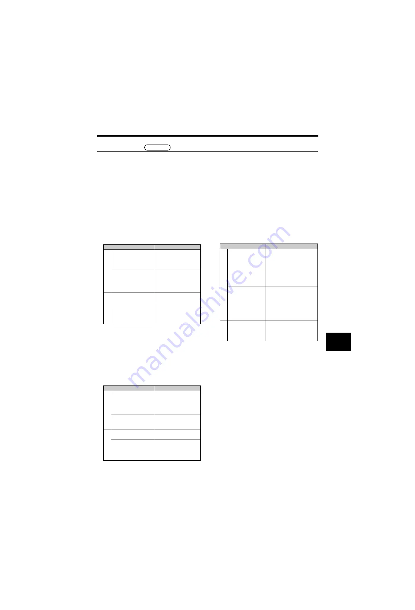
Countermeasure
Effect
In
ve
rt
e
r
Set the speed limit by [
Pr.
1 Maximum frequency
].
Vibration is avoided by
operating in the frequency
less than the vibration
enhancing frequency.
*1
Use the functions set by
[
Pr. 31 to 36 Frequency
jump
].
Operation at resonance
frequency is avoided
(resonance point cannot be
avoided during
acceleration/deceleration).
Sy
stem
Apply flexible coupling or
tire-shaped coupling.
Rotation vibration is
absorbed.
Strengthen the rigidity of
the machine and motor, or
place vibration-proof
rubber.
Natural frequency at
machine side is changed.
Countermeasure
Effect
In
ve
rt
e
r
Use the functions set by
[
Pr. 31 to 36 Frequency
jump
].
Operation at resonance
frequency is avoided
(resonance point cannot be
avoided during
acceleration/deceleration).
Change [
Pr. 72 PWM
frequency selection
] setting.
Resonance is avoided by
changing the cogging
torque.
*2
Sy
ste
m
Apply flexible coupling or
tire-shaped coupling.
Rotation vibration is
absorbed.
Strengthen the rigidity of
the machine and motor, or
place vibration-proof
rubber.
Natural frequency at
machine side is changed.
Countermeasure
Effect
In
ve
rt
e
r
Set [
Pr. 653 Speed
smoothing control
].
Inverter detects torque
fluctuation (including motor
rotor) in the mechanical system
and adjusts inverter's operation
frequency so that it will not be
affected by the mechanical
vibration,. This results in the
operation without resonance.
Reduce output voltage
(adjust [
Pr. 3
] and
[
Pr. 19
])
Motor slip is increased to
reduce torque fluctuation for
the speed fluctuation. In that
condition, inverter is less likely
to be affected by mechanic
vibration, and resonance is
avoided.
*3
S
yst
em
Strengthen the rigidity
of the machine and
motor, or place
vibration-proof rubber.
Natural frequency at machine
side is changed.
Summary of Contents for FR-A700 Series
Page 245: ...279 2 PARAMETER PARAMETER MEMO ...
Page 440: ...474 PARAMETER MEMO ...
Page 522: ...556 SELECTION MEMO ...


