521
SELECTION
S
E
LECTION
3
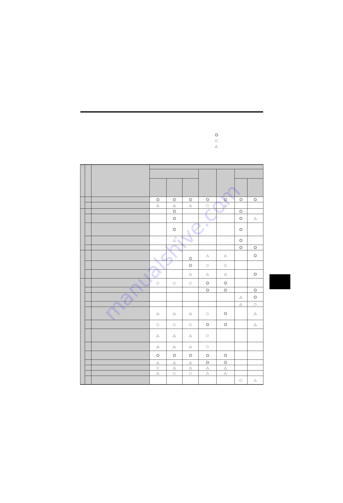
(3) Specific technique examples
1) Techniques and effects
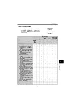
The following levels (estimated values) of effects are
expected for the technique examples (on the next page).
Use this data for reference when determining the priority of
actual techniques.
Symbol meanings
: Large effect
: Effect produced
: Small effect
— : No effect
Effects of EMI reduction techniques
Lo
cat
io
n
Sym
b
ol
Technique
EMI Propagation
Air propagated EMI
Electro-
magnetic
induction
interference
Electro-
static
induction
interference
Electrical path
propagated EMI
Radiation
from
inverter
Radiation
from
power
cables
Radiation
from
motor
cables
Power
cables
Leakage
current of
ground
cable
In
ve
rt
e
r
A Decrease carrier frequency [
Pr. 72
]
B Increase input S/W filter constant [
Pr. 74
]
—
—
In
put
s
ide
C Install capacitor type filter FR-BIF (-H)
—
—
—
—
—
D
Install common mode filter FR-BSF01 or
FR-BLF
—
—
—
—
E
Run power supply cables in metal conduit
or use shielded cables as power supply
cables
—
—
—
—
—
F
Install insulated transformer or noise
reduction transformer
—
—
—
—
—
G Separate power supply line
—
—
—
—
—
O
u
tput
side
H
Install common mode filter FR-BSF01 or
FR-BLF
—
—
—
I
Run output cables in metal conduit or use
shielded cables
—
—
—
—
J
Use 4-core cable as motor power line and
use one wire as ground cable
—
—
—
Connec
te
d equipment
K
Use twisted pair shielded cable as sensor
signal line
—
—
L Connect shield to common of sensor signal
—
—
—
—
M
Do not earth sensor power unit to control
box etc. directly
—
—
—
—
—
N Earth sensor power unit via capacitor
—
—
—
—
—
O
Use twisted pair shielded cables for signal
inputs and connect shield to common (input
terminal) SD
—
P
Use twisted pair shielded cables for speed
inputs and connect shield to terminal 5
—
Q
Insert ferrite cores available commercially
into speed input cables (output side of
mating equipment)
—
—
—
R
Lower impedance of output circuit of mating
equipment
—
—
—
S
Separate more than 30cm from inverter and
power line
—
—
T Do not run cables in parallel or together
—
—
U Provide masking shield
—
—
V Keep away from ground
—
—
W
Insert ferrite cores available commercially
in input side of mating equipment
—
—
—
—
—
Summary of Contents for FR-A700 Series
Page 245: ...279 2 PARAMETER PARAMETER MEMO ...
Page 440: ...474 PARAMETER MEMO ...
Page 522: ...556 SELECTION MEMO ...


