109
Function assignment of external terminal and control
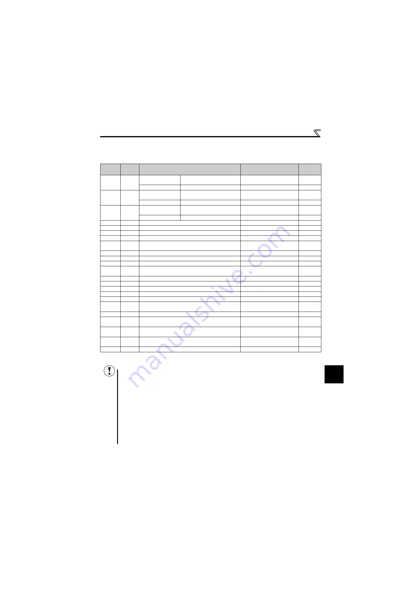
(1) Input terminal function assignment
Using
Pr. 178 to Pr. 182
, set the functions of the input terminals.
Refer to the following table and set the parameters:
∗1
When
Pr. 59 Remote function selection
≠
"0", the functions of the RL, RM and RH signals are changed as given in the table.
∗2
The OH signal turns on when the relay contact "opens".
(2) Response time of each signal
The response time of the X10 signal and MRS signal is within 2ms.
The response time of other signals is within 20ms.
Setting
Signal
Function
Related Parameters
Refer to
Page
0
RL
Pr. 59
= 0 (initial value)
Low-speed operation command
Pr. 4 to Pr. 6, Pr. 24 to Pr. 27
Pr.232 to Pr.239
Pr. 59
≠
0
Remote setting (setting clear)
Pr. 59
1
RM
Pr. 59
= 0 (initial value)
Middle-speed operation command
Pr. 4 to Pr. 6, Pr. 24 to Pr. 27,
Pr. 232 to Pr. 239
Pr. 59
≠
0
Remote setting (deceleration)
Pr. 59
2
RH
Pr. 59
= 0 (initial value)
High-speed operation command
Pr. 4 to Pr. 6, Pr. 24 to Pr. 27,
Pr. 232 to Pr. 239
Pr. 59
≠
0
Remote setting (acceleration)
Pr. 59
3
RT
Second function selection
Pr. 44 to Pr. 51
4
AU
Terminal 4 input selection
Pr. 267
5
JOG
Jog operation selection
Pr. 15, Pr. 16
7
OH
External thermal relay input
∗2
Pr. 9
8
REX
15-speed selection (combination with three speeds RL, RM,
RH)
Pr. 4 to Pr. 6, Pr. 24 to Pr. 27,
Pr. 232 to Pr. 239
10
X10
Inverter run enable signal (FR-HC, FR-CV connection)
Pr. 30, Pr. 70
12
X12
PU operation external interlock
Pr. 79
14
X14
PID control valid terminal
Pr. 127 to Pr. 134
16
X16
PU-external operation switchover (turning on X16 selects
external operation)
Pr. 79, Pr. 340
18
X18
V/F switchover (V/F control is exercised when X18 is on)
Pr. 80
24
MRS
Output stop
Pr. 17
25
STOP
Start self-holding selection
—
37
X37
Traverse function selection
Pr. 592 to Pr. 597
60
STF
Forward rotation (assigned to STF terminal
(Pr. 178)
only)
—
61
STR
Reverse rotation command (assigned to STR terminal
(Pr. 179)
only)
—
62
RES
Inverter reset
—
—
65
X65
PU/NET operation switchover (turning on X65 selects PU
operation)
Pr. 79, Pr. 340
66
X66
External/NET operation switchover (turning on X66 selects
NET operation)
Pr. 79, Pr. 340
67
X67
Command source switchover (turning on X67 makes
Pr. 338
and Pr. 339
commands valid)
Pr. 338, Pr. 339
9999
—
No function
—
—
NOTE
Changing the terminal assignment using
Pr.178 to Pr.182 (input terminal function selection)
may affect the other functions.
Make setting after confirming the function of each terminal.
One function can be assigned to two or more terminals. In this case, the terminal inputs are ORed.
The priorities of the speed commands are in order of jog > multi-speed setting (RH, RM, RL, REX) > PID (X14).
When the X10 signal (FR-HC, FR-CV connection-inverter operation enable signal) is not set or when the PU operation
external interlock (X12) signal is not assigned with
Pr.79 Operation mode selection
set to "7", the MRS signal shares this
function.
Use common terminals to assign multi-speeds (7 speeds) and remote setting. They cannot be set individually.
(Common terminals are used since these functions are designed for speed setting and need not be set at the same
time.)
When V/F control is selected by V/F switchover (X18 signal), second function is also selected at the same time.
Control between V/F and general-purpose magnetic flux can not be switched during operation. In case control is
switched between V/F and general-purpose magnetic flux, only second function is selected.
Turning the AU signal on makes terminal 2 (voltage input) invalid.
Summary of Contents for FR-D700 Series
Page 11: ...VII MEMO ...
Page 23: ...12 MEMO ...
Page 57: ...46 MEMO ...
Page 262: ...258 MEMO ...
Page 276: ...272 MEMO ...
Page 287: ...283 MEMO ...
Page 289: ......


