Wiring
Connection of stand-alone option units
FR-D700 SC EC
3 - 41
3.6.5
Connection of the power regeneration common converter FR-CV
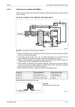
When connecting the power regeneration common converter (FR-CV), make connection so that
the inverter terminals (P/+, N/
−
) and the terminal symbols of the power regeneration common
converter (FR-CV) are the same.
Keep input terminals (R/L1, S/L2, T/L3) open. Incorrect connection will damage the inverter.
Do not insert an MCCB between the terminals P/+ and N/– (between P/L+ and P/+, between
N/L
−
and N/–). Opposite polarity of terminals N/–, P/+ will damage the inverter.
Always connect the power supply and terminals R/L11, S/L21, T/MC1. Operating the inverter
without connecting them will damage the power regeneration common converter.
Use Pr. 178 to Pr. 182 to assign the terminals used for the X10, RES signal.
Be sure to connect terminal RDYB of the FR-CV to the X10 signal or MRS signal assigned
terminal of the inverter, and connect terminal SE of the FR-CV to terminal SD of the inverter.
Without proper connecting, FR-CV will be damaged.
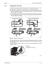
I002079E
Fig. 3-33:
Connection of the power regeneration common converter FR-CV
NOTES
The voltage phases of terminals R/L11, S/L21, T/MC1 and terminals R2/L1, S2/L2, T2/L3
must be matched.
Use sink logic when the FR-CV is connected. The FR-CV cannot be connected when source
logic (factory setting) is selected.
Do not remove a jumper across terminal P/+ and P1.
R/L
11
S/L
21
T/L
31
R2/L
12
S2/L
22
T2/L
32
R2/L
1
S2/L
2
T2/L
3
R/L
11
S/L
21
T/MC1
P/L+
U
V
W
PC
SD
X10
RES
SD
P24
SD
RDYB
RSO
SE
RDYA
N/L-
R/L1
S/L2
T/L3
P/+
N/–
MCCB
MC
1
Inverter
Dedicated stand-alone
reactor FR-CVL
Power regeneration
common converter FR-CV
3-phase AC
power supply
Motor
M
3~
Summary of Contents for FR-D720S SC EC
Page 2: ......
Page 4: ......
Page 24: ...Description of the case Product checking and part identification 1 4 ...
Page 108: ...Operation panel Operation 4 20 ...
Page 436: ...Setting for the parameter unit and operation panel Parameter 6 286 ...
Page 484: ...Measurements on the main circuit Maintenance and inspection 8 14 ...
Page 504: ...Specification change Appendix A 20 ...
Page 505: ......
Page 506: ......
Page 510: ...Index Appendix A 24 ...
Page 511: ......

