6
INSTALLATION
2.3 Installation Procedure
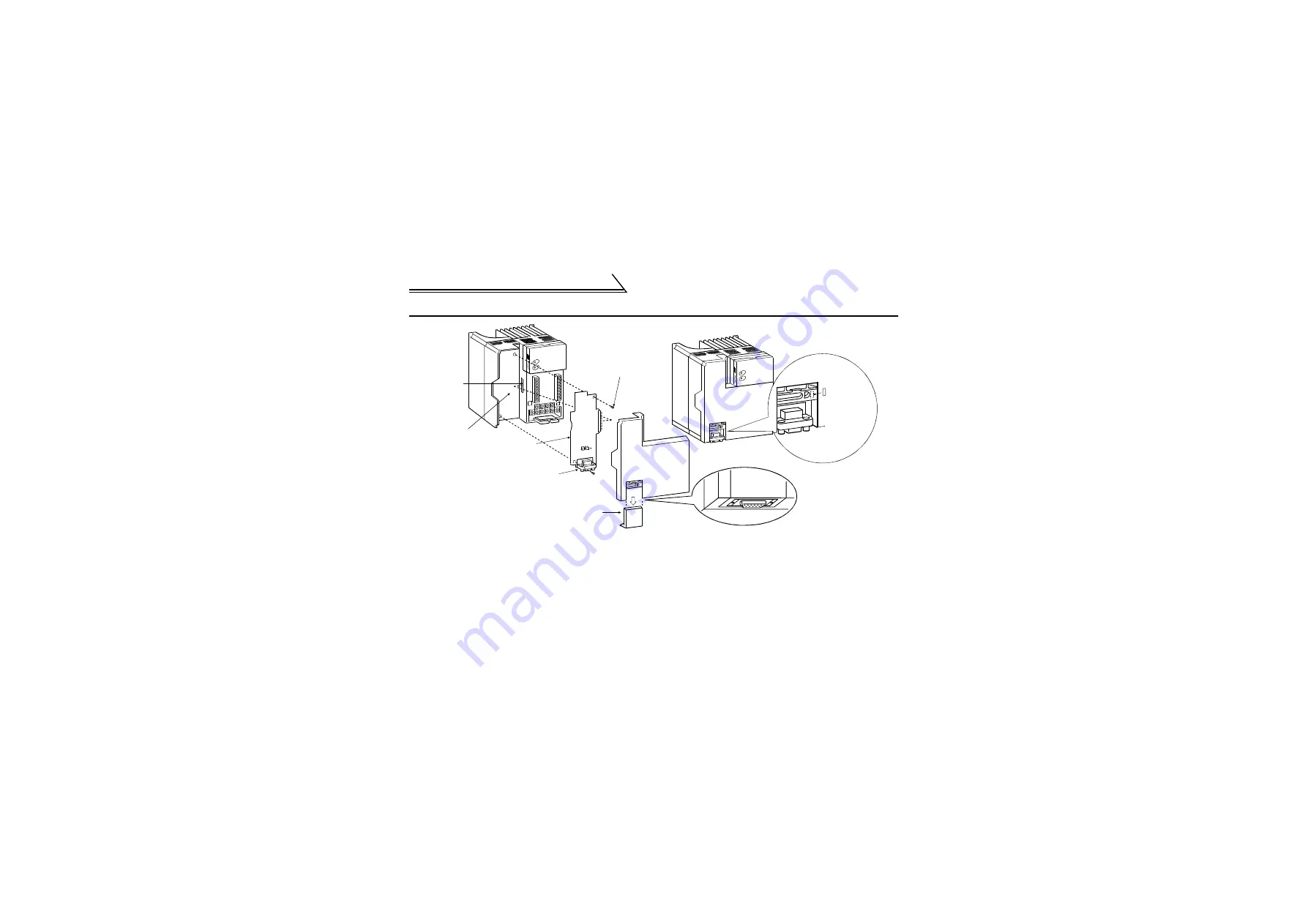
(1) Remove the front cover and option wiring port cover. (Refer to the inverter manual.)
(2) Remove the sponge from the inboard option connector, align the option unit connector with the inboard
option connector of the inverter, and securely insert it far enough into the inverter.
(3) Securely fix the two top and bottom places of the option unit to the inverter with the accessory mounting
screws. If the screw holes do not line up, the connector may not have been plugged snugly. Check for
looseness.
(4) Reinstall the front cover of the inverter. (Refer to the inverter manual.)
Profibus unit
(FR-E5NP)
Profibus connector
(Dsub9 pin connector)
Apply the
LED indication
sticker packed
with the
product.
Wiring port cover for
option plugged-in status
Cut out the bottom of the
cover before fitting.
Accessory screw
(2pcs.)
Wiring port cover
for option
FR-E5NP plugged-in status
Connector for
connection of
inboard option
Inboard option
mounting position


