background image

21

Wiring

2

INST

ALLA

TION AND WIRING

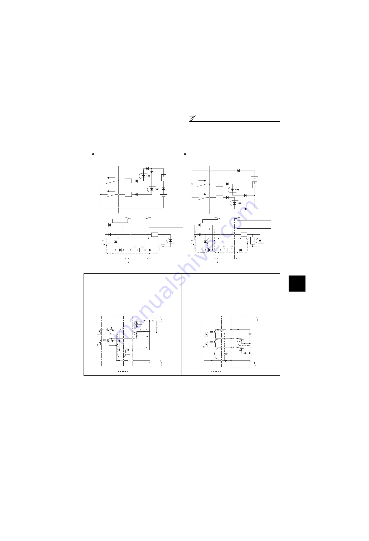
Sink logic and source logic

In sink logic, a signal switches on when a current flows from the corresponding signal input terminal.
Terminal SD is common to the contact input signals. Terminal SE is common to the open collector output signals.

In source logic, a signal switches on when a current flows into the corresponding signal input terminal.
Terminal PC is common to the contact input signals. Terminal SE is common to the open collector output signals.

When using an external power supply for transistor output

Sink logic type
Use terminal PC as a common terminal to prevent a
malfunction caused by undesirable current. (Do not
connect terminal SD of the inverter with terminal 0V of
the external power supply. When using terminals PC-
SD as a 24VDC power supply, do not install a power
supply in parallel in the outside of the inverter. Doing so
may cause a malfunction due to undesirable current.)

Source logic type
When using an external power supply for transistor
output, use terminal SD as a common to prevent
misoperation caused by undesirable current.

Current

PC

STF

R

STR

R

Source logic

Source
connector

Current

SD

STF

R

STR

R

Sink
connector

Sink logic

Current flow concerning the input/output signal 
when sink logic is selected

Current flow concerning the input/output signal 
when source logic is selected

DC input (source type)
<Example: AX80>

24VDC

RUN

SE

1

9

R

Inverter

R

Current flow

+

-

+

-

DC input (sink type)
<Example: AX40>

Inverter

24VDC

RUN

SE

1

9

R

R

Current flow

AY40 type 
transistor 
output unit

1

2

9

10

24VDC SD

PC

STR

STF

Inverter

24VDC
(SD)

9

Current flow

AY80 type 
transistor 
output unit

9

1

2

10

PC

STF

STR

SD

Inverter

24VDC
(SD)

24VDC

Current flow

Summary of Contents for FR-F 700 EC

Page 1: ...FR F 700 EC Frequency Inverter Instruction Manual Basic FR F740 00023 to 12120 EC INDUSTRIAL AUTOMATION MITSUBISHI ELECTRIC MITSUBISHI ELECTRIC Art no 158047 01 07 2005 IB NA 0600192ENG Version D ...

Page 2: ......

Page 3: ...1 4 4 When the rated motor frequency is 60Hz Pr 3 52 4 5 Change acceleration and deceleration time Pr 7 Pr 8 53 4 6 Energy saving operation Pr 60 54 4 7 Selection of the operation command and frequency command locations Pr 79 56 4 8 Parameter clear 57 4 9 All parameter clear 58 4 10 Parameter copy and parameter verification 59 TROUBLESHOOTING 61 5 1 List of alarm display 61 5 2 Causes and correcti...

Page 4: ...ntation is correct Prevent other conductive bodies such as screws and metal fragments or other flammable substance such as oil from entering the inverter As the inverter is a precision instrument do not drop or subject it to impact Use the inverter under the following environmental conditions Otherwise the inverter may be damaged 1 Temperature applicable for a short time e g in transit 2 2 9m s2 o...

Page 5: ...onitoring of output current and output voltage 31 3 2 5 First priority monitor 31 3 2 6 Setting dial push 31 3 3 Overheat protection of the motor by the inverter Pr 9 32 3 4 Start stop from the operation panel PU operation mode 33 3 4 1 Set the set frequency to operate example performing operation at 30Hz 33 3 4 2 Use the setting dial like a potentiometer to perform operation 34 3 4 3 Use switches...

Page 6: ...ve actions 62 5 3 Reset method of protective function 73 5 4 Correspondences between digital and actual characters 73 5 5 Check and clear of the alarm history 74 5 6 Check first when you have troubles 76 5 6 1 Motor does not rotate as commanded 76 5 6 2 Motor generates abnormal noise 76 5 6 3 Motor generates heat abnormally 76 5 6 4 Motor rotates in opposite direction 77 5 6 5 Speed greatly differ...

Page 7: ...ed to display the extended parameters 106 Appendix 2 2Extended parameter list 107 Appendix 3For customers who have replaced the older model with this inverter 130 Appendix 3 1Replacement of the FR F500 series 130 Appendix 3 2Replacement of the FR A100 EXCELENT series 131 Appendix 4 Instructions for UL and cUL 132 Appendix 5 Instructions for Compliance with the European Directives 134 Abbreviations...

Page 8: ... options Alarm lamp Lit when the inverter is in the alarm status major fault Capacity plate Inverter type Serial number Capacity plate Rating plate Combed shaped wiring cover EC FR F740 00126 EC 00126 Symbol 00023 to 12120 Displays the rated current Type Number FR F740 Symbol F740 Voltage Class Three phase 400V class Rating plate Inverter type Input rating Output rating Serial number FR F740 00126...

Page 9: ...case circuit breaker Power supply harmonics can be greatly suppressed Install this as required Greater braking capability is obtained Install this as required The breaker must be selected carefully since an in rush current flows in the inverter at power on Install a noise filter to reduce the electromagnetic noise generated from the inverter Effective in the range from about 1MHz to 10MHz When mor...

Page 10: ...32 FR F740 02600 EC 400AF 400A 400AF 400A S N220 160 FR F740 03250 EC 400AF 400A 600AF 500A S N300 185 FR F740 03610 EC 400AF 400A 600AF 500A S N300 220 FR F740 04320 EC 600AF 500A 600AF 600A S N400 250 FR F740 04810 EC 600AF 600A 600AF 600A S N600 280 FR F740 05470 EC 600AF 600A 800AF 800A S N600 315 FR F740 06100 EC 800AF 700A 800AF 800A S N600 355 FR F740 06830 EC 800AF 800A 800AF 800A S N600 4...

Page 11: ...ion panel FR F740 00620 EC or less Removal Reinstallation Installation hook Front cover Front cover 1 Loosen the installation screws of the front cover 2 Pull the front cover toward you to remove by pushing an installation hook using left fixed hooks as supports Front cover Front cover Front cover 1 Insert the two fixed hooks on the left side of the front cover into the sockets of the inverter 2 U...

Page 12: ...lation screws on the front cover 1 to remove the front cover 1 2 Loosen the installation screws of the front cover 2 3 Pull the front cover 2 toward you to remove by pushing an installation hook on the right side using left fixed hooks as supports Front cover 2 Front cover 2 Front cover 2 Front cover 1 1 Insert the two fixed hooks on the left side of the front cover 2 into the sockets of the inver...

Page 13: ...nces below Vertical Fix six positions for the FR F740 04320 to 08660 and fix eight positions for the FR F740 09620 to 12120 Clearances Ambient temperature and humidity Measurement position Measurement position Inverter Leave enough clearances and take cooling measures Humidity 90 RH maximum 01160 or less 01800 or more 5cm 5cm 5cm 10cm or more 10cm or more 5cm or more 5cm or more 10cm or more 10cm ...

Page 14: ...to use 2W1kΩ when the frequency setting signal is changed frequently 0 to 5VDC 0 to 10VDC selected 4 GND RS 485 terminals Data transmission Data reception 4 to 20mADC 4 selected 0 to 5VDC 0 to 10VDC 0 to 10VDC Analog signal output Frequency detection Open collector output common Sink source common Running Up to frequency Instantaneous power failure Overload Open collector output Terminal 4 input s...

Page 15: ...or push the fixing tab and pull the connector straight without pulling the cable or forcibly pulling the connector with the tab fixed When installing the connector also engage the fixing tab securely If it is difficult to disconnect the connector use a pair of long nose pliers etc CAUTION Fit the connector to either ON or OFF WARNING While power is on or when the inverter is running do not open th...

Page 16: ...ol circuit R1 L11 S1 L21 with the main circuit power R L1 S L2 T L3 on Doing so may damage the inverter The circuit should be configured so that the main circuit power R L1 S L2 T L3 is also turned off when the power supply for control circuit R1 L11 S1 L21 is off 00380 or less 60VA 00470 or more 80VA P N Brake unit connection Connect the brake unit FR BU BU and MT BU5 power regeneration common co...

Page 17: ...er supply Motor R L1 S L2 T L3 N P R1 L11 S1 L21 Screw size 00770 M6 00930 01160 M8 Screw size 00770 M6 00930 01160 M8 IM R L1 S L2 T L3 N P R1 L11 S1 L21 DC reactor Screw size M10 Screw size M4 Power supply Motor Jumper Charge lamp P Screw size 01800 M8 02160 02600 M10 Screw size 01800 M8 02160 M10 Screw size 01800 M8 02160 02600 M10 IM R L1 S L2 T L3 N P R1 L11 S1 L21 P P Screw size M4 Jumper Ch...

Page 18: ...ductor of the 05470 or more tighten a nut from the right side of the conductor When wiring two wires place wires on both sides of the conductor Refer to the drawing below For wiring use bolts nuts provided with the inverter Handling of the wiring cover FR F740 00470 00620 EC For the hook of the wiring cover cut off the necessary parts using a pair of long nose pliers etc IM R L1 S L2 T L3 N R1 L11...

Page 19: ...00 12 2 200 2 200 60 2 350 2 350 2 185 2 185 2 95 FR F740 07700 EC M12 M10 24 5 C2 200 C2 200 2 200 2 200 60 2 400 2 400 2 185 2 185 2 95 FR F740 08660 EC M12 M10 24 5 C2 250 C2 250 2 250 2 250 60 2 500 2 500 2 240 2 240 2 120 FR F740 09620 EC M12 M10 24 5 C2 250 C2 250 2 250 2 250 100 2 500 2 500 2 240 2 240 2 120 FR F740 10940 EC M12 M10 24 5 C2 200 C2 200 3 200 3 200 100 3 350 3 350 3 185 3 185...

Page 20: ... motor Take the following measures in this case 1 Connect the surge voltage suppression filter FR ASF H to the 01160 or less and the sine wave filter MT BSL BSC to the 01800 or more on the inverter output side 4 Cable size of the control circuit power supply terminal R1 L11 S1 L21 Terminal Screw Size M4 Cable size 0 75mm2 to 2mm2 Tightening torque 1 5N m Pr 72 PWM frequency selection Setting carri...

Page 21: ...arm output provided when protective function is activated Turn on the RES signal for more than 0 1s then turn it off Initial setting is for reset always By setting Pr 75 reset can be set to enabled only at an inverter alarm occurrence Recover about 1s after reset is cancelled 73 AU Terminal 4 input selection Terminal 4 is made valid only when the AU signal is turned on The frequency setting signal...

Page 22: ...ng signal terminal 2 1 or 4 and analog output terminal AM and CA Do not earth Type Terminal Symbol Terminal Name Description Rated Specifications Refer to Relay A1 B1 C1 Relay output 1 alarm output 1 changeover contact output indicates that the inverter protective function has activated and the output stopped Abnormal No conduction across B C Across A C Continuity Normal Across B C Continuity No c...

Page 23: ...RS 485 Transmission format Multidrop Communication speed 4800 to 38400bps Overall length 500m 22 RS 485 terminals TXD Inverter transmission terminal With the RS 485 terminals communication can be made through RS 485 Conforming standard EIA 485 RS 485 Transmission format Multidrop link Communication speed 300 to 38400bps Overall length 500m 22 TXD RXD Inverter reception terminal RXD SG Earth Loosen...

Page 24: ...nput terminals e g STF of the control circuit 5 Always apply a voltage to the alarm output terminals A B C via a relay coil lamp etc 6 It is recommended to use the cables of 0 75mm2 gauge for connection to the control circuit terminals If the cable gauge used is 1 25mm2 or more the front cover may be lifted when there are many cables running or the cables are run improperly resulting in an operati...

Page 25: ...ect the power supply terminals R1 L11 and S1 L21 of the control circuit to the primary side of the MC 1 Loosen the upper screws 2 Remove the lower screws 3 Remove the jumper 4 Connect the separate power supply cable for the control circuit to the lower terminals R1 L11 S1 L21 1 Remove the upper screws 2 Remove the lower screws 3 Remove the jumper 4 Connect the separate power supply cable for the c...

Page 26: ...f you do not remove the jumper 3 The voltage should be the same as that of the main control circuit when the control circuit power is supplied from other than the primary side of the MC 4 The power capacity is 60VA or more for 00380 or less 80VA or more for 00470 or more when separate power is supplied from R1 L11 S1 L21 5 When the power supply used with the control circuit is different from the o...

Page 27: ...e the control logic the jumper connector on the control circuit terminal block must be moved to the other position The output signals may be used in either the sink or source logic independently of the jumper connector position CAUTION Turn off the inverter power before switching a jumper connector SINK SOURC E SINK SOUR CE ...

Page 28: ...ply When using terminals PC SD as a 24VDC power supply do not install a power supply in parallel in the outside of the inverter Doing so may cause a malfunction due to undesirable current Source logic type When using an external power supply for transistor output use terminal SD as a common to prevent misoperation caused by undesirable current Current PC STF R STR R Source logic Source connector C...

Page 29: ...using a commercially available connector and cable as a parameter unit connection cable refer to Instruction Manual applied The inverter can be connected to the computer and FR PU04 Conforming standard EIA 485 RS 485 Transmission format Multidrop link Communication speed MAX 38400bps Overall length 500m Connection cable Twisted pair cable 4 paires Parameter unit connection cable FR CB2 option Oper...

Page 30: ...communication cable a user program can run and monitor the inverter or read and write to parameters For the Mitsubishi inverter protocol computer link operation communication can be performed with the PU connector and RS 485 terminal For the Modbus RTU protocol communication can be performed with the RS 485 terminal For further details refer to Instruction Manual applied PLC Multidrop link 32 inve...

Page 31: ...the inverter and motor are at a stop When the magnetic contactor is turned on while the inverter is operating overcurrent protection of the inverter and such will activate When an MC is provided to switch to a commercial power supply for example it is recommended to use commercial power supply inverter switchover operation Pr 135 to Pr 139 Instruction Manual applied REMARKS Since repeated inrush c...

Page 32: ... side This will cause the inverter to trip or the capacitor and surge suppressor to be damaged If any of the above devices is installed immediately remove it 8 Before starting wiring or other work after the inverter is operated wait for at least 10 minutes after the power supply has been switched off and check that there are no residual voltage using a tester or the like The capacitor is charged w...

Page 33: ...ng operation of frequent start stop of the inverter increase decrease in the temperature of the transistor element of the inverter may repeat due to a continuous flow of large current shortening the life from thermal fatigue Since thermal fatigue is related to the amount of current the life can be increased by reducing bound current starting current etc Decreasing current may increase the life How...

Page 34: ...FR PU04 PU Change frequency with ON OFF switches connected to terminals multi speed setting Perform frequency setting by a current output device Connection across terminals 4 5 Perform frequency setting by a voltage output device Connection across terminals 2 5 Set from the PU FR DU07 FR PU04 Change of frequency with ON OFF switches connected to terminals multi speed setting Perform frequency sett...

Page 35: ...ring mode PU Lit to indicate PU operation mode EXT Lit to indicate external operation mode NET Lit to indicate network operation mode Rotation direction indication REV Lit during reverse rotation FWD Lit during forward rotation Run command forward rotation Run command reverse rotation Stop operation Alarms can be reset Mode switchover Used to change each setting mode Unit indication Hz Lit to indi...

Page 36: ...ue change Parameter write is completed Parameter and a setting value flicker alternately Parameter clear Parameter all clear Alarm clear Parameter copy Example Example Frequency setting has been written and completed and frequency flicker Operation for displaying alarm history Past eight alarms can be displayed The latest alarm is ended by When no alarm history exists is displayed Operation mode s...

Page 37: ...t 0 extended mode parameter valid in Pr 160 User group read selection Set 10 or 11 key lock mode valid in Pr 161 Frequency setting key lock operation selection Functions valid even in the operation lock status Stop and reset with CAUTION Release the operation lock to release the PU stop by key operation 1 Screen at powering on The monitor display appears Display Operation Flicker Parameter setting...

Page 38: ...utput frequency monitor 3 2 6 Setting dial push Push the setting dial to display the set frequency currently set POINT Monitor display of output frequency output current and output voltage can be changed by pushing during monitoring mode 2 Independently of whether the inverter is running in any operation mode or at a stop the output current monitor appears by pressing 3 Press to show the output vo...

Page 39: ... connected to the inverter they cannot be protected by the electronic thermal relay function Install an external thermal relay to each motor When the difference between the inverter and motor capacities is large and the setting is small the protective characteristics of the electronic thermal relay function will be deteriorated In this case use an external thermal relay A special motor cannot be p...

Page 40: ...eration mode Why Check that 0 initial value is set in Pr 79 Operation mode selection Check that the start command is not on Change acceleration time Pr 7 Refer to page 53 Change deceleration time Pr 8 Refer to page 53 For example limit the motor speed to 50Hz maximum Set 50Hz in Pr 1 Refer to page 51 REMARKS Press to show the set frequency can also be used like a potentiometer to perform operation...

Page 41: ...e set by merely turning Display Operation PU indication is lit Flicker Parameter setting complete 7 Press to set The parameter number previously read appears 1 Screen at powering on The monitor display appears 2 Press to choose the PU operation mode 3 Press to choose the parameter setting mode 11 Turn until 50 00 appears The flickering frequency is the set frequency You need not press The frequenc...

Page 42: ...N ON ON ON ON Output frequency Hz Speed 1 High speed Speed 2 Middle speed Speed 3 Low speed Speed 4 Speed 5 Speed 6 Speed 7 Time RH RM RL Three phase AC power supply Motor Inverter R L1 S L2 T L3 U V W High speed Middle speed Low speed RH RM RL FR DU07 PC Display Operation Flicker Parameter setting complete Flickering The parameter number read previously appears 1 Screen at powering on The monitor...

Page 43: ...V lamp is not lit Why Check that wiring is correct Check the wiring once again Check for the Pr 79 setting once again Pr 79 must be set to 4 Refer to page 56 Change the frequency of the terminal RL RM and RH How Refer to page 43 to change the running frequency at each terminal in Pr 4 Multi speed setting high speed Pr 5 Multi speed setting middle speed and Pr 6 Multi speed setting low speed Flicke...

Page 44: ...t start Also if both switch turn on while running the inverter stops Flicker Parameter setting complete Flickering The parameter number read previously appears 8 Start Press the start switch or Operation status indication of FWD or REV flickers 1 Screen at powering on The monitor display appears 2 Press to choose the parameter setting mode 3 Turn until Pr 79 appears 4 Press to read the currently s...

Page 45: ...he frequency in calibration parameter C2 Terminal 2 frequency setting bias frequency Refer to Instruction Manual applied Stop Flickering Display Operation 10 Deceleration Turn the volume frequency setting potentiometer counterclockwise slowly to full The frequency value on the indication decreases according to Pr 8 Deceleration time unitl 0 00Hz is displayed and operation status indication of FWD ...

Page 46: ... reverse switch turn on the inverter will not start Also if both switch turn on while running the inverter stops Flickering The parameter number read previously appears Display Operation 8 Start Check that the terminal 4 input selection signal AU is on Press the start switch or FWD or REV of operation status indication flickers 7 Mode monitor check Press twice to choose the monitor frequency monit...

Page 47: ...eter C5 Terminal 4 frequency setting bias frequency Refer to Instruction Manual applied Stop Flickering Display Operation 10 Deceleration Perform 4mA input The frequency value on the indication decreases according to Pr 8 Deceleration time until 0 00Hz is displayed and the operation status indication of FWD or REV flickers The motor stops 11 Stop Press FWD or REV of the operation status indication...

Page 48: ...ve a start command Set 3 in Pr 79 External PU combined operation mode 1 Refer to page 33 for the set frequency by the operation panel Three phase AC power supply Motor Inverter R L1 S L2 T L3 U V W FR DU07 STR Forward rotation start Reverse rotation start STF PC 1 Screen at powering on The monitor display appears Display Operation 7 Turn the start switch STF or STR on The motor runs at the frequen...

Page 49: ... operation panel FR DU07 and are displayed alternately 1 Turn the start switch STF or STR off 2 The display can be reset by Display Operation Stop 10 Turn the start switch STF or STR off The motor decelerates according to Pr 8 Deceleration time to stop OFF Flicker Frequency setting complete 9 While the value is flickering press to set the frequency If you do not press the value flickers for about ...

Page 50: ... T L3 U V W High speed Middle speed Low speed RH RM RL Forward rotation start Reverse rotation start STF STR PC ON ON ON ON ON ON ON ON ON ON ON Output frequency Hz Speed 1 High speed Speed 2 Middle speed Speed 3 Low speed Speed 4 Speed 5 Speed 6 Speed 7 Time RH RM RL The parameter number read previously appears ON Display Operation 1 Power on operation mode check For the initial setting the inver...

Page 51: ... set in Pr 179 STR terminal function selection all are initial values How is the frequency setting from 4 to 7 speed The setting differs according to Pr 24 to Pr 27 multi speed setting Refer to Instruction Manual applied Perform multi speed operation higher than 8 speed How Use the REX signal to perform the operation Refer to Instruction Manual applied REMARKS External operation is fixed by settin...

Page 52: ...e volume frequency setting potentiometer counterclockwise slowly to full The frequency value of the indication decreases according to Pr 8 Deceleration time until 0 00Hz is displayed The motor stops 5 Stop Turn the start switch STF or STR off 1 Power on operation mode check For the initial setting the inverter operates in the external operation mode EXT when powering on Check that the operation co...

Page 53: ...z at 5V voltage input Set 40Hz in Pr 125 Set frequency at 0V using calibration parameter C2 and adjust the indicator using calibration parameter C0 Refer to Instruction Manual applied REMARKS As other adjustment methods of frequency setting voltage gain there are methods to adjust with a voltage applied to across terminals 2 5 and adjust at any point without a voltage applied Refer to Instruction ...

Page 54: ...he external operation mode EXT when powering on Check that the operation command indication is EXT If not displayed press to change to the external EXT operation mode If the operation mode still does not change set Pr 79 to change to the external operation mode Display Operation Forward rotation Reverse rotation Forward rotation Reverse rotation ON OFF ON Flickering Flickering Stop When both the f...

Page 55: ...rrent input Set 40Hz in Pr 126 Set frequency at 4mA using calibration parameter C5 and adjust the indicator using calibration parameter C0 Refer to Instruction Manual applied REMARKS As other adjustment methods of frequency setting voltage gain there are methods to adjust with a voltage applied to across terminals 4 5 and adjust at any point without a voltage applied Refer to Instruction Manual ap...

Page 56: ...to the inverter capacity 01160 or less 01800 or more 51 2 Minimum frequency 0 01Hz 0Hz 0 to 120Hz Set when the minimum output frequency need to be limited 3 Base frequency 0 01Hz 50Hz 0 to 400Hz Check the motor rating plate 52 4 Multi speed setting high speed 0 01Hz 50Hz 0 to 400Hz Set when changing the preset speed in the parameter with a terminal 43 5 Multi speed setting middle speed 0 01Hz 30Hz...

Page 57: ...ion thermal trip E THM Motor overload shut off and E THT Inverter overload shut off When an error E OC1 occurs release the start command and decrease the Pr 0 value 1 by 1 to reset Refer to page 66 POINT If the inverter still does not operate properly after the above measures adjust Pr 80 Simple magnetic vector control extended mode Refer to Instruction Manual applied Output voltage Pr 0 Pr 46 Set...

Page 58: ...t by When performing a high speed operation at 120Hz or more setting of Pr 18 High speed maximum frequency is necessary Refer to Instruction Manual applied CAUTION If the Pr 2 setting is higher than the Pr 13 Starting frequency value note that the motor will run at the set frequency according to the acceleration time setting by merely switching the start signal on without entry of the command freq...

Page 59: ...ange Pr 3 Base frequency to 60Hz according to the motor rated frequency 3 Press to choose the parameter setting mode Flicker Parameter setting complete 7 Press to set By turning you can read another parameter Press to show the setting again Press twice to show the next parameter 4 Turn until Pr 3 Base frequency appears 1 Screen at powering on The monitor display appears 2 Press to choose the PU op...

Page 60: ...eration time 00250 or more 15s 8 Deceleration time 00170 or less 10s 0 to 3600 360s Set the motor deceleration time 00250 or more 30s Changing example Change the Pr 7 Acceleration time setting from 5s to 10s Running frequency Acceleration time Deceleration time Time Pr 20 Pr 7 Pr 8 Output frequency Hz 50Hz 1 Screen at powering on The monitor display appears Display Operation 3 Press to choose the ...

Page 61: ...ration mode 4 Energy saving operation mode 9 Optimum excitation control mode REMARKS For applications a large load torque is applied to or machines repeat frequent acceleration deceleration an energy saving effect is not expected REMARKS When the motor capacity is too small as compared to the inverter capacity or two or more motors are connected to one inverter the energy saving effect is not expe...

Page 62: ...tting mode 4 Turn until Pr 60 appears Flicker Parameter setting complete 7 Press to set 5 Press to read the currently set value initial value appears 6 Turn to change it to the set value 8 Perform normal operation When you want to check the energy saving effect refer to the instruction manual applied to check the energy saving effect monitor PU indication is lit 2 Press to choose the PU operation ...

Page 63: ...e 2 Fixed to external operation mode Operation can be performed by switching between the external and NET operation mode External operation mode NET operation mode 3 External PU combined operation mode 1 Running frequency Start signal PU FR DU07 FR PU04 setting or external signal input multi speed setting across terminals 4 5 valid when AU signal turns on External signal input terminal STF STR 4 E...

Page 64: ...ode 1 Press is lit and the monitor 4 digit LED displays 0 Pr 79 0 initial value 2 Carry out operation from step 6 again 1 Screen at powering on The monitor display appears Display Operation 3 Press to choose the parameter setting mode Flicker Parameter setting complete 7 Press to set 5 Press to read the currently set value initial value appears PU indication is lit 2 Press to choose the PU operati...

Page 65: ...s lit and the monitor 4 digit LED displays 0 Pr 79 0 initial value 2 Carry out operation from step 6 again 1 Screen at powering on The monitor display appears Display Operation 3 Press to choose the parameter setting mode Flicker Parameter setting complete 7 Press to set 5 Press to read the currently set value initial value appears PU indication is lit 2 Press to choose the PU operation mode Press...

Page 66: ...rite again or check the values by parameter verification 1 Connect the operation panel to the copy source inverter Connect it during a stop Display Operation 2 Press to choose the parameter setting mode Flicker Parameter copy complete 6 Press to copy the source parameters to the operation panel 4 Press to to read the currently set value initial value appears Flicker Parameter copy complete 9 Press...

Page 67: ...0 series model error is displayed flickers Why Set frequencies etc may be different Check set frequencies 01160 or less 01800 or more Pr 989 Setting 10 100 Hold down to verify 2 Screen at powering on The monitor display appears Display Operation 7 Press to read the parameter setting of the verified inverter to the operation panel 1 Replace the operation panel on the inverter to be verified Replace...

Page 68: ...ervoltage 64 RB Regenerative brake prealarm 65 TH Electronic thermal relay function prealarm 65 PS PU stop 64 MT Maintenance signal output 65 CP Parameter copy 65 Minor fault FN Fan fault 66 Major fault E OC1 Overcurrent shut off during acceleration 66 E OC2 Overcurrent shut off during constant speed 66 E OC3 Overcurrent shut off during deceleration or stop 66 E OV1 Regenerative overvoltage shut o...

Page 69: ...ing operation with a value other than 2 writing is enabled independently of operation status in any operation mode is set in Pr 77 and the STF STR is on Check point 1 Check the Pr 77 setting Refer to Instruction Manual applied 2 Check that the inverter is not operating Corrective action 1 Set 2 in Pr 77 2 After stopping operation make parameter setting Operation Panel Indication Er3 Name Calibrati...

Page 70: ...tinue verification Make parameter verification again Refer to page 60 2 Check for an operation panel FR DU07 failure Please contact your sales representative Operation Panel Indication rE4 Name Model error Description 1 A different model was used for parameter write and verification during parameter copy 2 When parameter copy write is stopped after parameter copy read is stopped Check point 1 Chec...

Page 71: ...motor status Refer to page 50 2 Set a larger value in Pr 7 Acceleration time and Pr 8 Deceleration time Refer to page 53 3 Reduce the load weight 4 Try simple magnetic flux vector control Pr 80 5 Change the Pr 14 Load pattern selection setting 6 Set stall prevention operation current in Pr 22 Stall prevention operation level The initial value is 110 The acceleration deceleration time may change In...

Page 72: ... used for the THP signal output assign the function by setting 8 positive logic or 108 negative logic in any of Pr 190 to Pr 196 output terminal function selection Refer to Instruction Manual applied Check point 1 Check for large load or sudden acceleration 2 Is the Pr 9 Electronic thermal O L relay setting is appropriate Refer to page 32 Corrective action 1 Reduce the load weight or the number of...

Page 73: ...cation 2 When E OC1 is always lit at starting disconnect the motor once and start the inverter If E OC1 is still lit contact your sales representative 3 Check the wiring to make sure that output short circuit does not occur 4 Perform a correct stall prevention operation Refer to Instruction Manual applied 5 Set base voltage rated voltage of the motor etc in Pr 19 Base frequency voltage Refer to In...

Page 74: ...sudden speed reduction Corrective action Increase the deceleration time Set the deceleration time which matches the inertia of moment of the load Decrease the braking duty Use regeneration avoidance function Pr 882 to Pr 886 Refer to Instruction Manual applied Use the brake unit or power regeneration common converter FR CV as required Operation Panel Indication E THT FR PU04 Inv Overload Name Inve...

Page 75: ... power failure occurrence Corrective action Remedy the instantaneous power failure Prepare a backup power supply for instantaneous power failure Set the function of automatic restart after instantaneous power failure Pr 57 Refer to Instruction Manual applied Operation Panel Indication E BE FR PU04 Br Cct Fault Name Brake transistor alarm detection internal circuit error Description This function s...

Page 76: ...connection cable Corrective action Remedy the earth fault portion Operation Panel Indication E LF FR PU04 Name Output phase failure Description This function stops the inverter output if one of the three phases U V W on the inverter s output side load side opens Check point Check the wiring Check that the motor is normal Check that the capacity of the motor used is not smaller than that of the inv...

Page 77: ...2 Take measures against noises if there are devices producing excess electrical noises around the inverter If the problem still persists after taking the above measure please contact your sales representative or distributor Operation Panel Indication E PE FR PU04 Corrupt Memry Name Parameter storage devide alarm control circuit board Description A fault occurred in parameters stored EEPROM failure...

Page 78: ...Check for a short circuit in the PU connector cable 2 Check that the RS 485 terminals are connected correctly Corrective action 1 Check the PU and cable 2 Check the connection of the RS 485 terminals Operation Panel Indication E P24 FR PU04 E P24 Name 24VDC power output short circuit Description When the 24VDC power output from the PC terminal is shorted this function shuts off the power output At...

Page 79: ...log input error Description Appears when 30mA or more is input or a voltage 7 5V or more is input with the terminal 2 4 set to current input Check point Check the setting of Pr 73 Analog input selection and Pr 267 Terminal 4 input selection Refer to Instruction Manual applied Corrective action Either give a frequency command by current input or set Pr 73 Analog input selection or Pr 267 Terminal 4...

Page 80: ...peration panel Operation 1 Using the operation panel press to reset the inverter Enabled only when the inverter protective function is activated major fault Refer to page 66 for major fault Operation 2 Switch power off once then switch it on again Operation 3 Turn on the reset signal RES for more than 0 1s If the RES signal is kept on Err appears flickers to indicate that the inverter is in a rese...

Page 81: ... change Operation for displaying alarm history Eight past alarms can be displayed with the setting dial The latest alarm is ended by When no alarm exists is displayed Output current Flickering Output voltage Flickering Flickering Flickering Press the setting dial Press the setting dial Press the setting dial Energization time Alarm history number The number of past alarms is displayed Flickering O...

Page 82: ...lection 1 Screen at powering on The monitor display appears Display Operation 2 Press to choose the parameter setting mode 3 appears Flicker Alarm history clear complete 6 Press to set 4 Press to read the currently set value initial value appears Press to show the setting again Press twice to show the next parameter Press to read another parameter 5 Turn to change it to the setting value The param...

Page 83: ...ter settings Check that the Pr 79 Operation mode selection setting is correct Check that the bias and gain calibration parameter C2 to C7 settings are correct Check that the Pr 13 Starting frequency setting is not greater than the running frequency Check that frequency settings of each running frequency such as multi speed operation are not zero Check that especially the Pr 1 Maximum frequency is ...

Page 84: ... that the load is not too heavy Check that the Pr 0 Torque boost setting is correct Check that the Pr 3 Base frequency setting is correct Check that the Pr 14 Load pattern selection setting is appropriate Check that the Pr 19 Base frequency voltage setting is correct 5 6 8 Speed does not increase Check that the maximum frequency Pr 1 setting is correct If you want to run the motor at 120Hz or more...

Page 85: ... the mode to the PU operation mode For other values 1 to 4 6 7 the operation mode is limited accordingly 5 6 11 Operation panel FR DU07 display is not operating Check that the operation panel is connected to the inverter securely 5 6 12 POWER lamp is not lit Check that wiring is securely performed and installation is correct 5 6 13 Parameter write cannot be performed Make sure that operation is no...

Page 86: ...n circuit terminals P N of the inverter is not more than 30VDC using a tester etc 6 1 Inspection item 6 1 1 Daily inspection Basically check for the following faults during operation 1 Motor operation fault 2 Improper installation environment 3 Cooling system fault 4 Unusual vibration and noise 5 Unusual overheat and discoloration During operation check the inverter input voltages using a tester 6...

Page 87: ...uminum electrolytic capacitor 1 Check for liquid leakage Contact the manufacturer 2 Check for safety valve projection and bulge Contact the manufacturer 3 Visual check and judge by the life check of the main circuit capacitor Refer to page 81 Relay contactor Check that the operation is normal and no chatter is heard Contact the manufacturer Control circuit protective circuit Operation check 1 Chec...

Page 88: ...it circuit has reached the life alarm output level Parts Judgement level Main circuit capacitor 85 of the initial capacity Control circuit capacitor Estimated 10 life remaining Inrush current limit circuit Estimated 10 life remaining Power on 100 000 times left Cooling fan Less than 40 of the predetermined speed Pr 255 decimal Bit binary Inrush Current Limit Circuit Life Cooling Fan Life Main Circ...

Page 89: ...cted b Terminal R1 L11 S1 L21 or DC power supply is connected to the terminals P and N c Switch power on during measuring d The motor is not connected to the inverter e The motor is running The motor is coasting f The motor capacity is two rank smaller as compared to the inverter capacity g The inverter is at an alarm stop or an alarm occurred while power is off h The inverter output is shut off w...

Page 90: ...arts replacement Replacement years for when the yearly average ambient temperature is 40 C without corrosive gas flammable gas oil mist dust and dirt etc CAUTION Do not use solvent such as acetone benzene toluene and alcohol as they will cause the inverter surface paint to peel off The display etc of the operation panel FR DU07 and parameter unit FR PU04 are vulnerable to detergent and alcohol The...

Page 91: ...00470 00620 MMF 12D24DS RP1 BKO CA1619H01 1 00770 MMF 09D24TS RP1 BKO CA1640H01 2 00930 to 01800 MMF 12D24DS RP1 BKO CA1619H01 2 02160 to 03610 3 04320 04810 9LB1424H5H03 3 05470 to 06830 4 07700 08660 5 09620 to 12120 9LB1424S5H03 6 The FR F740 00023 to 00052 are not provided with a cooling fan Removal 00083 to 03610 1 Push the hooks from above and remove the fan cover 2 Disconnect the fan connec...

Page 92: ...he fan cover For installation of the FR F740 04320 to 12120 refer to the previous page AIR FLOW Fan side face CAUTION Installing the fan in the opposite air flow direction can cause the inverter life to be shorter 00083 00126 00170 to 00380 00470 00620 00770 to 03610 2 Insert hooks until you hear a click sound 1 Insert hooks into holes 00083 00126 2 Insert hooks until you hear a click sound 1 Inse...

Page 93: ...rming the orientation of the fan reinstall the fan so that the arrow on the left of AIR FLOW faces up 2 Install fans referring to the above figure Fan Fan connection connector Front cover 1 04320 04810 Fan connection connector Fan 05470 or more AIR FLOW Fan side face CAUTION Installing the fan in the opposite air flow direction can cause the inverter life to be shorter ...

Page 94: ...e that the capacitor has reached its life when the measured capacitance of the capacitor reduced below 80 of the rating 4 Relays To prevent a contact fault etc relays must be replaced according to the cumulative number of switching times switching life 6 1 8 Inverter replacement The inverter can be replaced with the control circuit wiring kept connected Before replacement remove the wiring cover o...

Page 95: ...ts for commercial frequency are used for measurement measure the following circuits with the instruments given on the next page Examples of Measuring Points and Instruments CAUTION Before performing the insulation resistance test on the external circuit disconnect the cables from all terminals of the inverter so that the test voltage is not applied to the inverter For the continuity test of the co...

Page 96: ...e V2 Across U V V W and W U Rectifier type AC voltage meter 1 Moving iron type cannot measure Difference between the phases is within 1 of the maximum output voltage Output side current I2 U V and W line currents Moving iron type AC ammeter 2 Difference between the phases is 10 or lower of the rated inverter current Output side power P2 U V W and U V V W Electrodynamic type single phase wattmeter ...

Page 97: ...8 547 464 610 518 683 580 770 654 866 736 962 817 1094 929 1212 1030 Overload current rating 4 LD 120 60s 150 3s 50 C inverse time characteristics SLD 110 60s 120 3s 40 C inverse time characteristics Voltage 5 Three phase 380 to 500V Power supply Rated input AC voltage frequency Three phase 380 to 500V 50Hz 60Hz Permissible AC voltage fluctuation 323 to 528V 50Hz 60Hz Permissible frequency fluctua...

Page 98: ...ation switchover PU NET operation switchover External NET operation switchover command source switchover Operational functions Maximum and minimum frequency settings frequency jump operation external thermal relay input selection polarity reversible operation automatic restart after instantaneous power failure operation original operation continuation at an instantaneous power failure commercial p...

Page 99: ... during constant speed overcurrent during deceleration overvoltage during acceleration overvoltage during constant speed overvoltage during deceleration inverter protection thermal operation motor protection thermal operation heatsink overheat instantaneous power failure occurrence undervoltage input phase failure motor overload output side earth fault overcurrent output phase failure external the...

Page 100: ...38 00052 00083 00126 EC FR F740 00170 00250 00310 00380 EC Unit mm Unit mm 260 150 144 125 45 5 6 140 5 7 5 7 5 245 2 φ6 hole The FR F740 00023 to 00052 EC are not provided with a cooling fan H1 H D1 D 2 φ6 hole 7 5 220 195 211 10 6 7 5 Inverter Type H H1 D D1 FR F740 00170 00250 EC 260 245 170 84 FR F740 00310 00380 EC 300 285 190 101 5 ...

Page 101: ...R F740 00770 00930 01160 EC Unit mm Unit mm 10 230 250 380 10 10 400 190 10 5 101 5 250 2 φ10 hole W2 W W1 H D 2 φd hole H1 550 10 3 2 Inverter Type W W1 W2 H H1 d D FR F740 00770 EC 325 270 10 530 10 10 195 FR F740 00930 01160 EC 435 380 12 525 15 12 250 ...

Page 102: ... φ12 hole 15 10 3 2 12 Inverter Type W W1 H H1 D FR F740 01800 EC 435 380 525 550 250 for M6 screw 4 installation hole for M6 screw Earth ground terminal Rating plate 2 terminal E P1 P P1 P for M12 bolt Within D W1 W H1 10 H 10 DC reactor Type W W1 H H1 D Mass kg FR HEL H90K FR F740 01800 EC 150 130 340 310 190 20 ...

Page 103: ... hole DC reactor Type W W1 H H1 D S S1 Mass kg FR HEL H110K FR F740 02160 EC 150 130 340 310 195 M6 M6 22 FR HEL H132K FR F740 02600 EC 175 150 405 370 200 M8 M6 26 FR HEL H160K FR F740 03250 EC 175 150 405 370 205 M8 M6 28 FR HEL H185K FR F740 03610 EC 175 150 405 370 240 M8 M6 29 E P1 P P1 P W1 W Rating plate for S screw 4 installation hole for S1 screw Earth ground terminal Within D for M12 bol...

Page 104: ...1 D S S1 S2 φ Mass kg FR HEL H220K FR F740 04320 EC 175 150 405 370 240 M8 M6 M6 M12 30 FR HEL H250K FR F740 04810 EC 190 165 440 400 250 M8 M8 M8 M12 35 FR HEL H280K FR F740 05470 EC 190 165 440 400 255 M8 M8 M8 M16 38 FR HEL H315K FR F740 06100 EC 210 185 495 450 250 M10 M8 M8 M16 42 FR HEL H355K FR F740 06830 EC 210 185 495 450 250 M10 M8 M8 M16 46 E P1 P P1 P W1 W H1 10 H 10 Earth ground termi...

Page 105: ...22 194 1300 1330 315 12 315 E P P1 P1 P 75 40 40 500 10 455 10 220 195 Rating plate 2 M8 eye nut 2 terminal 4 15 hole Remove the eye nut after installation of the product Earth ground terminal for M8 screw Within 250 Within 235 4 installation hole for M10 screw DC reactor Type Mass kg FR HEL H400K FR F740 07700 EC 50 FR HEL H450K FR F740 08660 EC 57 ...

Page 106: ...27 4 5 P P1 P P1 E 40 75 40 150 215 D1 10 D 10 Remove the eye nut after installation of the product Rating plate 2 terminal 4 15 hole Earth ground terminal for M12 screw Within 245 Within H 2 M12 eye nut 4 installation hole for M10 screw DC reactor Type H D D1 Mass kg FR HEL H500K FR F740 09620 EC 345 455 405 67 FR HEL H560K FR F740 10940 EC 360 460 410 85 FR HEL H630K FR F740 12120 EC 360 460 410...

Page 107: ...ction connector FR ADP Outline drawing Panel cutting dimension drawing 78 50 44 72 3 3 81 3 3 16 25 3 2max 72 44 21 20 22 27 8 6 5 φ4 hole Outline drawing Panel cutting dimension drawing Select the installation screws whose length will not exceed the effective depth of the installation screws threads 40 23 75 11 75 81 5 1 25 1 5 13 17 16 5 1 5 125 72 15 10 5 18 5 40 80 48 24 13 20 21 5 14 5 5 M3 s...

Page 108: ... be protruded outside the enclosure using a heatsink protrusion attachment FR A7CN For a panel cut dimension drawing and an installation procedure of the heatsink protrusion attachment FR A7CN to the inverter refer to a manual of heatsink protrusion attachment FR A7CN01 to 10 7 4 2 Protrusion of heatsink of the FR F740 04320 or more 1 Panel cutting Cut the panel of the enclosure according to the i...

Page 109: ...er to the front side as shown on the right When changing the installation frames make sure that the installation orientation is correct FR F740 04320 04810 07700 or more Two installation frames each are attached to the upper and lower part of the inverter Remove the rear side installation frame on the upper and lower side of the inverter as shown on the right Upper installation frame Lower install...

Page 110: ... mist dust etc Be careful not to drop screws dust etc into the inverter and cooling fan section Inverter Inside the enclosure Enclosure Exhausted air Installation frame Dimension of the outside of the enclosure Cooling wind D1 Inverter Type D1 mm FR F740 04320 04810 185 FR F740 05470 to 12120 184 For the FR F740 05470 or more there are finger guards behind the enclosure Therefore the thickness of ...

Page 111: ...86 Selection and protection of a motor Motor protection from overheat electronic thermal relay function Pr 9 Pr 51 Use the constant torque motor applied motor Pr 71 Motor brake and stop operation DC injection brake Pr 10 to Pr 12 Selection of regeneration unit Pr 30 Pr 70 Selection of motor stopping method Pr 250 Decelerate the motor to a stop at instantaneous power failure Pr 261 to Pr 266 Functi...

Page 112: ...r 174 Control of parameter write by communication Pr 342 Selection of operation mode and operation location Operation mode selection Pr 79 Operation mode when power is on Pr 79 Pr 340 Operation command source and speed command source during communication operation Pr 338 Pr 339 Selection of the NET mode operation control source Pr 550 Selection of the PU mode operation control source Pr 551 Commun...

Page 113: ...een at powering on The monitor display appears Display Operation 3 Press to choose the parameter setting mode 4 Turn until Pr 160 appears Flicker Parameter setting complete 7 Press to set PU indication is lit 2 Press to choose the PU operation mode Press twice to show the next parameter By turning you can read another parameter Press to show the setting again The parameter number read previously a...

Page 114: ... the inverter capacity 01160 or less 01800 or more Base frequency voltage 3 Base frequency 0 01Hz 50Hz 0 to 400Hz Set the frequency when the motor rated torque is generated 50Hz 60Hz 19 Base frequency voltage 0 1V 8888 0 to 1000V Set the base voltage 8888 95 of power supply voltage 9999 Same as power supply voltage 47 Second V F base frequency 0 01Hz 9999 0 to 400Hz Set the base frequency when the...

Page 115: ...ent 6 The setting depends on the inverter capacity 01160 or less 01800 or more 51 Second electronic thermal O L relay 0 01 0 1A 7 9999 0 to 500A 0 to 3600A 7 Made valid when the RT signal is on Set the rated motor current 7 The setting depends on the inverter capacity 01160 or less 01800 or more 9999 Second electronic thermal O L relay invalid DC injection brake 10 DC injection brake operation fre...

Page 116: ...vention operation invalid 0 1 to 120 The stall prevention operation level can be set 49 Second stall prevention operation frequency 0 01Hz 0Hz 0 Second stall prevention operation invalid 0 01 to 400Hz Set the frequency at which stall prevention operation of Pr 48 is started 9999 Pr 48 is valid when the RT signal is on 66 Stall prevention operation reduction starting frequency 0 01Hz 60Hz 0 to 400H...

Page 117: ...ke unit Power regeneration converter 2 High power factor converter power regeneration common converter High power factor converter 70 Special regenerative brake duty 0 1 0 0 to 10 You can set the brake duty when a brake unit or power regeneration converter is used Setting can be made for the 01800 or more Avoid mechanical resonance points frequency jump 31 Frequency jump 1A 0 01Hz 9999 0 to 400Hz ...

Page 118: ...d decimal position 563 Energization time carrying over times 1 0 0 to 65535 The numbers of cumulative energization time monitor exceeded 65535h is displayed Reading only 564 Operating time carrying over times 1 0 0 to 65535 The numbers of operation time monitor exceeded 65535h is displayed Reading only 891 Cumulative power monitor digit shifted times 1 9999 0 to 4 Set the number of times to shift ...

Page 119: ...110 0 to 120 Consider the rated inverter current as 100 and set the stall prevention operation level during restart operation 299 Rotation direction detection selection at restarting 1 9999 0 without rotation direction detection 1 with rotation direction detection 9999 When Pr 78 0 the rotation direction is detected When Pr 78 1 2 the rotation direction is not detected 611 Acceleration time at a r...

Page 120: ...mal characteristics of the Mitsubishi constant torque motor 2 Thermal characteristic of standard motor Adjustable 5 points V F 20 Mitsubishi standard motor SF JR 4P 1 5kW or less Carrier frequency and SoftPWM selection 72 PWM frequency selection 1 2 0 to 15 0 to 6 25 12 PWM carrier frequency can be changed The setting displayed is in kHz Note that 0 indicates 0 7kHz 15 indicates 14 5kHz and 25 ind...

Page 121: ...y delay filter time constant for the analog input can be set A larger setting results in a larger filter Reset selection disconnected PU detection 75 Reset selection disconnected PU detection PU stop selection 1 14 0 to 3 14 to 17 100 to 103 114 to 117 You can select the reset input acceptance disconnected PU FR DU07 connector detection function and PU stop function and reset restriction 01800 or ...

Page 122: ...c flux vector control set the capacity of the motor used 13 The setting depends on the inverter capacity 01160 or less 01800 or more 9999 V F control is performed 90 Motor constant R1 0 001Ω 0 01mΩ 9999 0 to 50Ω 0 to 400mΩ 14 Used to set the motor primary resistance value Normally setting is not necessary 14 The setting depends on the inverter capacity 01160 or less 01800 or more 9999 Use the Mits...

Page 123: ...between data transmission to the inverter and response 9999 Set with communication data 124 PU communication CR LF presence absence selection 1 1 0 Without CR LF 1 With CR 2 With CR LF 331 RS 485 communication station number 1 0 0 to 31 0 to 247 Set the inverter station number same specifications as Pr 117 When 1 Modbus RTU protocol is set in Pr 551 the setting range within parenthesis is applied ...

Page 124: ... of terminal 4 input gain maximum 241 Analog input display unit switchover 1 0 0 Displayed in Select the unit for analog input display 1 Displayed in V mA C2 902 Terminal 2 frequency setting bias frequency 0 01Hz 0Hz 0 to 400Hz Set the frequency on the bias side of terminal 2 input C3 902 Terminal 2 frequency setting bias 0 1 0 0 to 300 Set the converted of the bias side voltage current of termina...

Page 125: ... the stability deteriorates e g hunting occurs Gain K 1 proportional band 9999 No proportional control 130 PID integral time 0 1s 1s 0 1 to 3600s Time required for only the integral I action to provide the same manipulated variable as that for the proportional P action As the integral time decreases the set point is reached earlier but hunting occurs more easily 9999 No integral control 131 PID up...

Page 126: ...it actually turns on 138 Commercial power supply operation switchover selection at an alarm 1 0 0 Inverter output is stopped motor coast at inverter fault 1 Operation is automatically switched to the commercial power supply operation at inverter fault Not switched when an external thermal error occurs 139 Automatic switchover frequency between inverter and commercial power supply operation 0 01Hz ...

Page 127: ... operation selection 1 0 0 Operation continues when the Y12 signal is on 1 The inverter is brought to an alarm stop when the Y12 signal is on E CDO 154 Refer to Pr 22 and Pr 23 Selection of action conditions of the second function 155 RT signal reflection time selection 1 0 0 Second function is immediately made valid with on of the RT X9 signal 10 Second function is valid only during the RT signal...

Page 128: ...al DC injection brake start 14 PID control valid terminal 16 PU external operation switchover 24 Output stop 25 Start self holding selection 37 Traverse function selection 60 Forward rotation command assigned to STF terminal Pr 178 only 61 Reverse rotation command assigned to STR terminal Pr 179 only 62 Inverter reset 63 PTC thermistor input assigned to AU terminal Pr 184 only 64 PID forward rever...

Page 129: ...on 71 Commercial power supply side motor 1 connection RO1 72 Commercial power supply side motor 2 connection RO2 73 Commercial power supply side motor 3 connection RO3 74 Commercial power supply side motor 4 connection RO4 75 Inverter side motor 1 connection RIO1 76 Inverter side motor 2 connection RIO2 77 Inverter side motor 3 connection RIO3 78 Inverter side motor 4 connection RIO4 90 190 Life a...

Page 130: ...otor stopping method 250 Stop selection 0 1s 9999 0 to 100s The motor is coasted to a stop when the preset time elapses after the start signal is turned off When 1000s to 1100s is set Pr 250 setting 1000 s later the motor coasts to stop STF signal Forward rotation start STR signal Reverse rotation start 1000 to 1100s STF signal Start signal STR signal Forward reverse signal 9999 When the start sig...

Page 131: ...an be decelerated to a stop 2 When undervoltage or a power failure occurs the inverter can be decelerated to a stop If power is restored during a power failure the inverter accelerates again 262 Subtracted frequency at deceleration start 0 01Hz 3Hz 0 to 20Hz Normally operation can be performed with the initial value unchanged But adjust the frequency according to the magnitude of the load specific...

Page 132: ...rminal can be switched on and off 497 Remote output data 2 1 0 0 to 4095 To determine the maintenance time of parts 503 Maintenance timer 1 0 0 1 to 9998 Display the cumulative energization time of the inverter in 100h increments Reading only Writing the setting of 0 clears the cumulative energization time 504 Maintenance timer alarm output set time 1 9999 0 to 9998 Setthe time taken until when th...

Page 133: ...tion time 0 1s 1s 0 to 3600s You can set the acceleration time for increasing the output frequency of the inverter if a motor disconnection occurs under advanced PID control 9999 The output frequency is not forcibly changed 584 Auxiliary motor 1 starting frequency 0 01Hz 50Hz 0 to 400Hz Set the frequency to connect an auxiliary motor 585 Auxiliary motor 2 starting frequency 0 01Hz 50Hz 0 to 400Hz ...

Page 134: ...nction valid 883 Regeneration avoidance operation level 0 1V DC760V 300 to 800V Set the bus voltage level at which regeneration avoidance operates When the bus voltage level is set to low overvoltage error will be less apt to occur However the actual deceleration time increases 884 Regeneration avoidance at deceleration detection sensitivity 1 0 0 to 5 Set sensitivity to detect the bus voltage cha...

Page 135: ...y saving monitor 9999 No function 897 Power saving monitor average time 1 9999 0 Average for 30 minutes 1 to 1000h Average for the set time 9999 No function 898 Power saving cumulative monitor clear 1 9999 0 Cumulative monitor value clear 1 Cumulative monitor value hold 10 Cumulative monitor continue communication data upper limit 9999 9999 Cumulative monitor continue communication data upper limi...

Page 136: ... 1 1 0 Without buzzer 1 With buzzer Contrast adjustment of the parameter unit 991 PU contrast adjustment 1 58 0 to 63 Contrast adjustment of the LCD of the parameter unit FR PU04 can be performed 0 Light 63 Dark Parameter clear parameter copy Pr CL Parameter clear 1 0 0 1 Setting 1 returns all parameters except calibration parameters to the initial values ALLC All parameter clear 1 0 0 1 Setting 1...

Page 137: ...e FR F700 series can not be used with the FR F500 series terminals 3 Instructions for continuous use of the FR PU04 parameter unit 1 For the FR F700 series many functions parameters have been added When setting these parameters the parameter name and setting range are not displayed Parameter list change list initial value list initial value list 2 and parameter clear of the HELP function can not b...

Page 138: ...ing Pr 199 was cleared Substitutable with the copy function of the operation panel FR DU07 Intelligent optimum acceleration deceleration Pr 60 setting 3 and Pr 61 to Pr 63 Function was cleared For deceleration time overvoltage alarm can be avoided with regeneration avoidance function Pr 882 to Pr 885 Automatic torque boost Pr 38 Pr 39 Automatic torque boost was cleared because of addition of Simpl...

Page 139: ...C and round crimping terminals Crimp the crimping terminals with the crimping tool recommended by the terminal maker 3 Short circuit ratings 01160 or less Suitable For Use in A Circuit Capable Of Delivering Not More Than 65kA rms Symmetrical Amperes 528V Maximum 01800 or more Suitable For Use in A Circuit Capable Of Delivering Not More Than 65kA rms Symmetrical Amperes 550V Maximum Appendix 4 Inst...

Page 140: ...lectronic thermal relay function is reset by inverter power reset and reset signal input Avoid unnecessary reset and power off When multiple motors are operated by a single inverter protection cannot be provided by the electronic thermal relay function Install an external thermal relay to each motor When the difference between the inverter and motor capacities is large and the setting is small the...

Page 141: ...For use as a product compliant with the Low Voltage Directive use PVC cable whose size is indicated on page 12 Use the moulded case circuit breaker and magnetic contactor which conform to the EN or IEC Standard When using an earth leakage current breaker use a residual current operated protective device RCD of type B breaker which can detect both AC and DC If not provide double or reinforced insul...

Page 142: ...MEMO ...

Page 143: ...Although this product was manufactured under conditions of strict quality control you are strongly advised to install safety devices to prevent serious accidents when it is used in facilities where breakdowns of the product are likely to cause a serious accident Please do not use this product for loads other than three phase induction motors Print Date Manual Number Revision May 2004 IB NA 0600192...

Page 144: ...us Phone 370 0 52323 101 Fax 370 0 52322 980 e mail powel utu lt EUROPEAN REPRESENTATIVES Intehsis Srl MOLDOVA Bld Traian 23 1 MD 2060 Kishinev Phone 373 0 22 66 4242 Fax 373 0 22 66 4280 e mail intehsis mdl net Koning Hartman b v NETHERLANDS Donauweg 2 B NL 1000 AK Amsterdam Phone 31 0 20 587 76 00 Fax 31 0 20 587 76 05 e mail info koningenhartman com Beijer Electronics AS NORWAY Teglverksveien 1...

Reviews: